
The Clock on Arduino Dilemma: Internal Timers vs. External RTCs
When makers first attempt to integrate a reliable clock on Arduino projects, they inevitably hit a wall. Whether you are building a weather data logger, an automated greenhouse irrigation system, or a precision chronometer, timing is everything. However, a fundamental misunderstanding of how microcontrollers handle time leads to countless forum posts about drifting clocks, reset errors, and I2C bus lockups.
To effectively troubleshoot timing issues, you must first understand the hardware limitations of the standard ATmega328P (found in the Uno and Nano). These boards do not possess a dedicated, battery-backed Real-Time Clock (RTC). Instead, they rely on millis() and micros() functions, which are driven by the main system clock. On official Arduino boards, this clock is sourced from a ceramic resonator (typically the Murata CSTCE16M0V53), which has a tolerance of roughly ±0.5%. While fine for blinking LEDs, a 0.5% drift equates to 432 seconds (7.2 minutes) of error per day. Furthermore, the moment power is cut, the internal timer resets to zero.
To achieve true timekeeping, you must interface an external RTC module via the I2C bus or use a modern 32-bit ARM board with a built-in RTC domain. Below, we break down the most critical failure modes when setting up a clock on Arduino environments and provide exact, component-level fixes.
Fault 1: I2C Bus Hanging and the 1970 Epoch Error
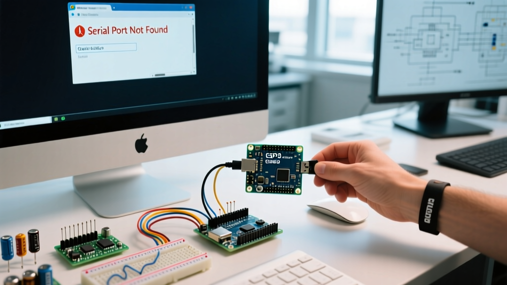
The most common symptom of a failing RTC integration is the serial monitor endlessly printing 1970-01-01 00:00:00 or 2000-01-01 00:00:00. This is not a broken clock; it is a complete failure of I2C communication. The microcontroller is failing to read the registers and is defaulting to the Unix epoch or the library's fallback zero-date.
The Pull-Up Resistor Oversight
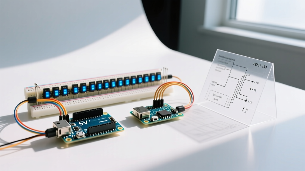
The I2C protocol requires an open-drain configuration, meaning the bus lines (SDA and SCL) must be pulled high to the logic voltage. While many breakout boards include 10kΩ surface-mount pull-up resistors, 10kΩ is often too weak for reliable communication over long wires or in electrically noisy environments, especially when operating at 5V.
- The Fix: If your wires exceed 15 centimeters, or if you are sharing the I2C bus with multiple sensors, add external 4.7kΩ pull-up resistors between the SDA/SCL lines and the 5V pin. If you are using a 3.3V board (like the Arduino Nano 33 IoT or ESP32), use 2.2kΩ resistors to ensure fast enough rise times on the signal edges.
- Address Verification: Ensure your code is polling the correct hexadecimal address. The DS1307 and DS3231 are hardcoded to
0x68. Run an I2C scanner sketch (available in the Arduino IDE examples under Wire > I2CScanner) to verify the hardware handshake before loading your RTC library.
Fault 2: Severe Time Drift on DS1307 Modules
If your clock on Arduino setups is losing or gaining several minutes a week, you are likely using the ubiquitous, ultra-cheap DS1307 module (often recognized by the red ZS-042 PCB). The DS1307 relies on an external 32.768 kHz tuning-fork crystal. These crystals exhibit a parabolic temperature coefficient, meaning they drift significantly as ambient temperatures move away from the 25°C calibration point.
According to Analog Devices technical documentation, a standard DS1307 can drift up to 5 minutes per month at room temperature, and drastically more in outdoor enclosures where temperatures swing between 0°C and 50°C.
The Upgrade Path: DS3231 TCXO
The definitive fix for environmental drift is upgrading to the DS3231. The DS3231 integrates a Temperature-Compensated Crystal Oscillator (TCXO) and a temperature sensor directly into the IC package. It actively adjusts the oscillator frequency to maintain an accuracy of ±2 PPM (parts per million) from 0°C to +40°C. This translates to a maximum drift of roughly 1 minute per year, effectively solving environmental timing errors without requiring software compensation.
Fault 3: The Rechargeable Battery Hazard (LIR2032 vs CR2032)
CRITICAL HARDWARE WARNING: Never insert a standard, non-rechargeable CR2032 lithium coin cell into a cheap ZS-042 DS3231/DS1307 module without modifying the board first. Doing so creates a severe fire and component failure hazard.
Most inexpensive RTC modules sourced from overseas marketplaces are designed around the LIR2032, which is a rechargeable lithium-ion coin cell. To support this, the PCB includes a charging circuit (usually a simple diode and resistor network connected to the 5V VCC line) that pushes up to 4.2V into the battery socket.
If you insert a standard CR2032 (which is primary, non-rechargeable and rated for 3.0V), the module will attempt to charge it. This causes the CR2032 to overheat, vent toxic gases, or rupture, while simultaneously pushing 4.2V into the RTC's VBAT pin, which can degrade the silicon over time.
How to Fix the Charging Circuit
- Flip the RTC module over and locate the surface-mount components near the battery holder.
- Identify the diode (usually marked
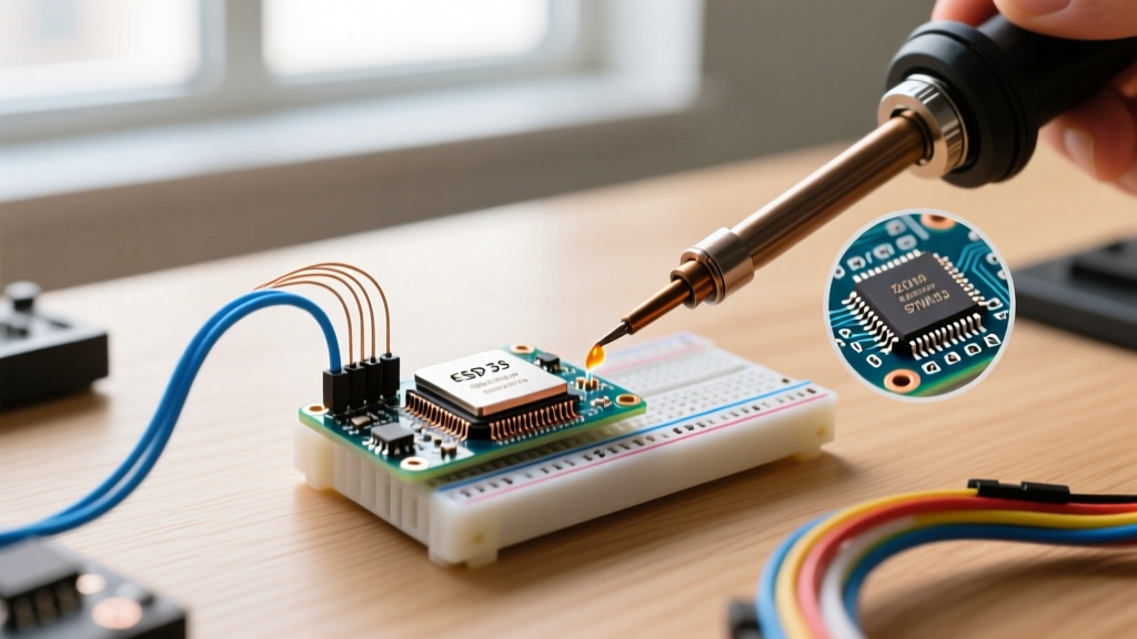
D1) or the charging resistor (often markedR2orR3with a value around 200Ω). - Using a fine-tipped soldering iron and tweezers, carefully desolder and remove the diode or resistor to physically break the charging path.
- Verify with a multimeter that the voltage at the battery holder positive terminal reads 0V when the module is connected to USB power, confirming the circuit is disabled.
For a comprehensive hardware walkthrough and wiring diagrams, the Adafruit DS3231 Precision RTC guide remains an industry-standard reference for safe module integration.
RTC Module Comparison Matrix (2026 Market Data)
Choosing the right hardware prevents 90% of software troubleshooting. Below is a comparison of the most common RTC modules used in maker projects today.
| Module IC | Accuracy (Typical) | Temperature Comp. | I2C Address | Avg. Price (2026) |
|---|---|---|---|---|
| DS1307 | ±20 PPM (Drifts heavily) | No | 0x68 | $1.50 - $2.50 |
| DS3231 (Standard) | ±2 PPM (0°C to 40°C) | Yes (Internal TCXO) | 0x68 | $3.00 - $5.00 |
| DS3231MZ | ±5 PPM (-40°C to 85°C) | Yes (Industrial) | 0x68 | $8.00 - $12.00 |
| PCF8523 | ±20 PPM (User Calibrated) | Software Offset Only | 0x68 | $2.50 - $4.00 |
Advanced Calibration: Tuning the DS3231 Aging Offset
Even with a TCXO, crystal aging causes slight frequency shifts over months of continuous operation. The DS3231 features an Aging Offset register (Address 0x10h) that allows you to manually trim the oscillator frequency in software.
According to the Arduino Wire library reference, you can write directly to this register using I2C commands. Each Least Significant Bit (LSB) in the two's complement register adjusts the frequency by approximately 0.1 PPM.
- To speed up the clock: Add a positive value to the aging offset register.
- To slow down the clock: Add a negative value (two's complement format).
Pro-Tip: Do not attempt to calibrate the aging offset until the module has been running continuously for at least 72 hours. The internal temperature compensation algorithm requires time to map the thermal mass of the PCB and the local environment. Calibrating too early will result in compounding errors once the thermal equilibrium shifts.
Beyond the ATmega: Utilizing the SAMD21/SAMD51 Built-in RTC
If you are migrating away from the Uno and using modern 32-bit boards like the Arduino Zero, Nano 33 IoT, or MKR series, you are working with ARM Cortex-M0+ or M4 processors (SAMD21/SAMD51). These chips feature a dedicated, low-power RTC domain built directly into the silicon.
However, a common troubleshooting trap is assuming the built-in RTC works out-of-the-box like an external module. The internal RTC requires a dedicated backup voltage supply to maintain time during main power loss. On the Arduino Nano 33 IoT, for example, you must supply 3.3V to the specific VBAT pin (often tied to a specific analog pin or dedicated pad) and connect an external 32.768 kHz crystal to the XIN32/XOUT32 pins if the board variant does not route the internal high-speed clock divider to the RTC peripheral. Failing to wire the VBAT pin will result in the clock resetting every time the USB cable is disconnected, mimicking the exact failure mode of an ATmega328P without an external module.
Summary Troubleshooting Checklist
Before tearing apart your wiring harness, run through this definitive checklist to isolate your clock on Arduino faults:
- Verify I2C Pull-ups: Measure SDA/SCL with a multimeter; they should read VCC (5V or 3.3V) when idle.
- Check Battery Voltage: A CR2032 should read >2.8V. If it reads 3.3V or higher, your charging circuit is active and destroying the cell.
- Confirm Library Initialization: Ensure
rtc.begin()is returningtruein yoursetup()loop before attempting to read time data. - Inspect for Cold Solder Joints: The 32.768 kHz through-hole crystals on cheap modules are notorious for brittle solder joints that break under minor mechanical stress, instantly killing the oscillator.
By understanding the physical hardware limitations and addressing the electrical nuances of the I2C bus and power delivery, you can transform a frustrating, drifting timer into a bulletproof, precision timekeeping system.