
The 'Quick Blink' Trap: Why Workflow Matters
Most introductory tutorials on how to connect an LED to Arduino follow the exact same pattern: grab a random 220-ohm resistor, plug a 5mm red LED into a breadboard, and write a delay(1000) loop. While this works for a five-minute classroom exercise, it instills terrible engineering habits. As projects scale from a single indicator light to complex, multi-sensor embedded systems with dozens of status LEDs, this ad-hoc approach leads to blocked execution loops, GPIO burnout, and spaghetti code.
In 2026, with the Arduino Uno R4 WiFi (powered by the Renesas RA4M1) serving as the modern maker standard at roughly $27.50, understanding the underlying electrical and architectural workflow is critical. This guide replaces guesswork with a structured, production-ready workflow for LED integration, covering pre-flight calculations, hardware optimization, non-blocking software architecture, and scalable multiplexing.
Phase 1: Component Selection & Pre-Flight Calculations
The most common failure mode in beginner circuits is LED burnout or dim output due to incorrect current limiting. Never rely on the 'magic 220-ohm' rule. Different LED chemistries have vastly different forward voltage (Vf) and forward current (If) requirements.
Standard 5mm LED Specifications Matrix
| LED Color / Type | Typical Vf (Volts) | Target If (mA) | Calculated Resistor (at 5V Logic) | Standard E12 Resistor Value |
|---|---|---|---|---|
| Red (e.g., Lite-On LTL-307EE) | 2.1V | 20mA | 145 Ω | 150 Ω |
| Green / Yellow | 2.2V | 20mA | 140 Ω | 150 Ω |
| Blue / Pure Green | 3.2V | 20mA | 90 Ω | 100 Ω |
| White / UV | 3.4V | 20mA | 80 Ω | 82 Ω |
Workflow Step: Always use a tool like LED Calc or manual Ohm's Law (R = (Vsource - Vf) / If) before selecting components. Furthermore, verify resistor power dissipation. For a 150Ω resistor dropping 2.9V at 20mA, the power dissipated is P = I² × R = 0.06W. A standard 1/4W (0.25W) carbon film resistor provides a safe 4x safety margin.
Phase 2: Hardware Assembly & Breadboard Optimization
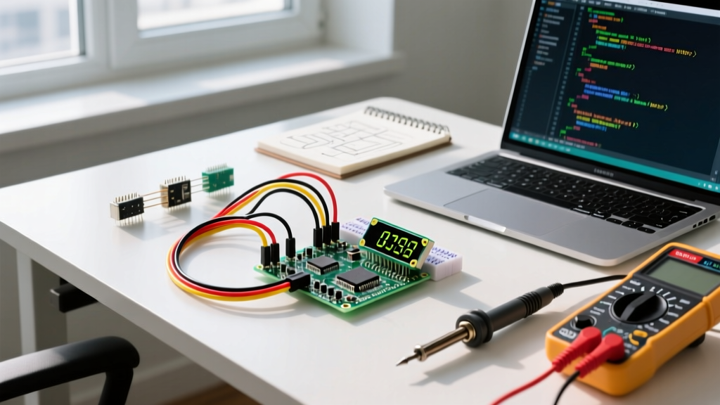
When prototyping how to connect an LED to Arduino on a solderless breadboard, wire management directly impacts your debugging speed. A chaotic nest of jumper wires hides loose connections and causes intermittent flickering.
Pro-Tip: Abandon standard pre-cut jumper wire kits for power and ground routing. Invest in a wire stripper and use 22 AWG solid-core hookup wire to create custom-length, flush-routed bus lines. This prevents accidental wire pulling when swapping microcontrollers.
Standardized Color-Coding Protocol
- Red: VCC / 5V Power
- Black: GND (Ground)
- Yellow / Orange: Digital GPIO Signals (to the LED anode via resistor)
- Green: Analog / PWM Signals
Always place the current-limiting resistor on the anode (positive) side of the LED. While electrically placing it on the cathode side works identically in a simple series circuit, standardizing on the anode side makes troubleshooting with a multimeter significantly easier, as you can probe the resistor's output to verify logic-high voltage before the LED drop.
Phase 3: Software Architecture (Non-Blocking Execution)
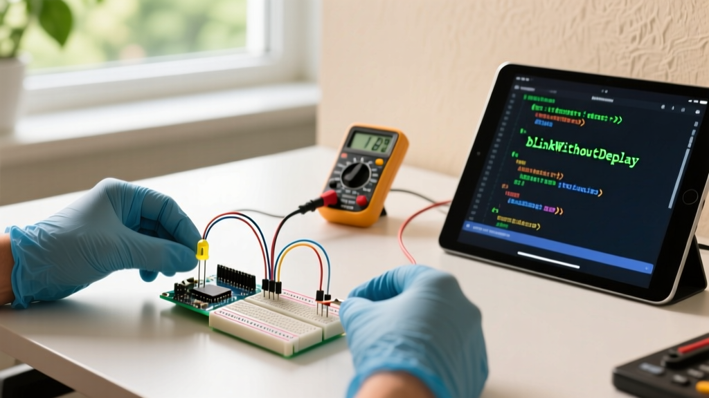
The delay() function halts the microcontroller's CPU. If your LED blinks using delay(1000), your Arduino cannot read sensors, process serial data, or update displays during that second. Optimizing your software workflow requires adopting a state-machine approach using millis().
The BlinkWithoutDelay Paradigm
Instead of pausing the CPU, track the passage of time. This allows the LED to blink concurrently with other tasks.
unsigned long previousMillis = 0;
const long interval = 1000;
int ledState = LOW;

void loop() {
  unsigned long currentMillis = millis();

  // Check if it's time to toggle the LED
  if (currentMillis - previousMillis >= interval) {
    previousMillis = currentMillis;
    ledState = (ledState == LOW) ? HIGH : LOW;
    digitalWrite(LED_PIN, ledState);
  }

  // CPU is free to execute other sensor readings here
}
PWM Fading Note: If you are utilizing Pulse Width Modulation for LED fading via analogWrite(), be aware of hardware differences. The classic ATmega328P operates PWM at roughly 490Hz (or 980Hz on pins 5 and 6). The modern Renesas RA4M1 on the Uno R4 supports 12-bit resolution (0-4095) compared to the older 8-bit (0-255), requiring code adjustments for smooth logarithmic fading curves.
Phase 4: Scaling Beyond the GPIO Limit
A critical bottleneck when learning how to connect an LED to Arduino is discovering the hardware current limits. The Uno R4 has a strict absolute maximum rating of 20mA per I/O pin, and a total package current limit that prevents you from lighting up 30 LEDs simultaneously at full brightness.
Scaling Decision Matrix
| Project Scale | Recommended Hardware Solution | Approx. Component Cost (2026) | Key Advantage |
|---|---|---|---|
| 1 - 8 LEDs | Direct GPIO Connection | $0.05 (Resistors) | Simplicity, minimal wiring. |
| 8 - 64 LEDs | 74HC595 Shift Registers | $0.15 per IC | Expands 3 GPIO pins to 8 outputs per chip; daisy-chainable. |
| 16+ High-Power LEDs | TLC5940 Constant Current Sink | $1.60 per IC | Eliminates current-limiting resistors; provides 4096-step PWM per channel. |
| 1W+ Star PCB LEDs | Logic-Level MOSFET (e.g., IRLZ44N) | $0.80 per MOSFET | Allows 5V GPIO to safely switch 12V/24V high-current LED arrays. |
For intermediate scaling, the Texas Instruments 74HC595 shift register is the industry standard. By utilizing the SPI or bit-banged shiftOut protocols, you can control dozens of LEDs using only three Arduino pins (Data, Clock, Latch), completely bypassing the microcontroller's internal current limitations.
Troubleshooting Edge Cases & Failure Modes
Even with an optimized workflow, hardware anomalies occur. Use this diagnostic matrix to resolve common integration issues rapidly:
- LED Glows Dimly When GPIO is LOW: You are likely experiencing induced voltage from adjacent high-current wires, or the GPIO pin is configured as an
INPUTrather thanOUTPUTin your setup routine, causing it to float. EnsurepinMode(pin, OUTPUT)is explicitly declared. - Microcontroller Randomly Resets: You have exceeded the total VCC/GND current limit of the voltage regulator or the MCU die. The onboard 5V regulator on an Arduino Uno can typically only supply 500mA to 800mA depending on the input voltage and thermal dissipation. If your LED array draws more, power the LEDs from an external 5V buck converter, sharing a common ground with the Arduino.
- High-Frequency Flickering on Camera: Standard PWM frequencies (~500Hz) cause visible banding on smartphone cameras. To fix this for photography or video applications, you must reconfigure the MCU's internal timers to push the PWM frequency above 20kHz (ultrasonic), which requires direct register manipulation on AVR chips or specific timer configurations on ARM/Renesas cores.
Summary Checklist for Production
- Calculate exact resistor values based on specific LED datasheet Vf/If.
- Route breadboard wiring using flush 22 AWG solid core and strict color codes.
- Replace all
delay()functions withmillis()state machines. - Offload high LED counts to shift registers or constant current drivers.
- Verify total system current draw against the board's voltage regulator limits.
By treating LED integration as a structured engineering workflow rather than an afterthought, you ensure your Arduino projects remain robust, scalable, and ready for real-world deployment.