
The Offline Advantage: Why Local MCU Speech Recognition?
When designing voice-controlled embedded systems in 2026, relying on cloud-based APIs introduces unacceptable latency (often 800ms to 1.5s round-trip) and privacy vulnerabilities. For industrial automation, smart home relays, and automotive DIY projects, offline Arduino speech recognition is the definitive solution. By processing acoustic signatures directly on the microcontroller or a dedicated DSP shield, you eliminate Wi-Fi dependencies and achieve sub-200ms command execution.
This configuration guide focuses on the industry-standard Elechouse Speech Recognition Module V3, detailing exact wiring protocols, UART configuration, and memory management. We will also contrast this with modern neural-network alternatives like the ESP32-S3 ESP-SR framework for advanced makers.
Hardware Selection Matrix: Dedicated DSP vs. Neural MCU
Choosing the right hardware depends on your command count, latency requirements, and budget. Below is a technical comparison of the top offline speech recognition solutions available for Arduino and ESP32 ecosystems.
| Module / Framework | Architecture | Max Active Commands | Avg Latency | Price Range (USD) |
|---|---|---|---|---|
| Elechouse V3 Module | Dedicated ASIC DSP | 15 (80 stored in Flash) | ~300ms | $22 - $28 |
| ESP32-S3 (ESP-SR) | RISC-V + Cadence Fusion F1 DSP | 200+ (MultiNet Model) | ~150ms | $8 - $12 (Dev Board) |
| DFRobot Gravity Voice | Dedicated DSP | 17 (Fixed/Custom) | ~350ms | $35 - $40 |
For pure Arduino Uno/Mega users, the Elechouse V3 is the most robust plug-and-play option. For ESP32 users willing to compile heavy machine learning models, the ESP32-S3 with native ESP-SR support offers vastly superior noise rejection and wake-word capabilities.
Wiring the Elechouse V3: Avoiding the 3.3V Logic Trap
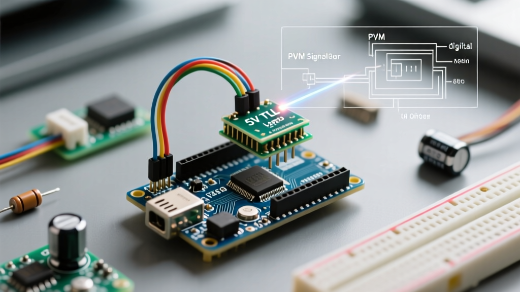
The most common failure mode in Arduino speech recognition projects using the Elechouse V3 is logic-level mismatching. The V3 module operates at 5V logic. While it will communicate flawlessly with a 5V Arduino Uno or Mega2560, connecting its TX/RX pins directly to a 3.3V microcontroller (like the ESP32, Teensy 4.1, or Arduino Due) will cause long-term degradation of the MCU's UART RX pin, or immediate logic faults due to voltage threshold misalignment.
The BSS138 Level Shifter Solution
Never use a simple resistor voltage divider for UART lines; the parasitic capacitance of high-value resistors will round off the square waves at 9600 baud, causing packet loss. Instead, use a BSS138 MOSFET-based bidirectional logic level converter (costing roughly $2 to $4).
- VCC (HV): Connect to 5V (from Arduino/Buck Converter)
- VCC (LV): Connect to 3.3V (from ESP32/Teensy)
- TX (Module) to RX (MCU): Route through one channel of the BSS138.
- RX (Module) to TX (MCU): Route through the second channel.
For a comprehensive breakdown of why MOSFET-based level shifters outperform resistor dividers in high-speed serial communication, refer to the SparkFun Logic Level Conversion tutorial.
Step-by-Step UART Configuration & Command Grouping
The Elechouse V3 communicates via standard UART at 9600 baud, 8 data bits, no parity, 1 stop bit (8N1). The official library abstracts the hex-frame protocol, but understanding the underlying memory architecture is critical for complex projects.
Managing the 15-Command Group Limit
Beginners often hit a wall when trying to load 30 custom voice commands into their sketch. The V3 module can store up to 80 custom voice signatures in its non-volatile flash memory, but its active DSP RAM can only process 15 commands simultaneously. To bypass this, you must configure your sketch to use 'Group Loading'.
Think of groups as contextual menus. You load 'Group 1' (e.g., System Wake, Main Menu). When the user says 'Lighting Control', the MCU triggers a serial command to the V3 module to swap the active RAM bank to 'Group 2' (e.g., Lights On, Lights Off, Dim). This swap takes approximately 50ms.
#include <SoftwareSerial.h>
#include <VoiceRecognitionV3.h>

VR myVR(2, 3); // RX, TX pins

void setup() {
  myVR.begin(9600);
  // Load Group 1 (Commands 0-14)
  myVR.loadgroup(1);
}
Proper management of the Arduino Serial buffer is also required. Always clear the serial buffer before initiating a group swap to prevent ghost commands from triggering immediately upon the new group loading.
Advanced Alternative: ESP32-S3 and ESP-SR Framework
If your 2026 project requires continuous listening, wake-word detection (e.g., 'Hi ESP'), and natural language command parsing without manual group swapping, the Elechouse V3 will not suffice. Instead, utilize the ESP32-S3-WROOM-1 module paired with Espressif's native ESP-SR (Speech Recognition) framework.
The ESP32-S3 features a dedicated Cadence Fusion F1 DSP core designed specifically for neural network acceleration. However, configuring ESP-SR requires strict hardware prerequisites:
- PSRAM Requirement: You must use an ESP32-S3 variant with at least 2MB of PSRAM (8MB Octal PSRAM is highly recommended). The MultiNet acoustic models require roughly 1.2MB of RAM just to load the inference engine.
- I2S Microphone Interface: Unlike the analog electret mic on the Elechouse V3, ESP-SR requires a digital I2S MEMS microphone array (like the INMP441 or SPH0645LM4H) to provide the high-fidelity PCM data the neural network expects.
- Compiler Configuration: You must enable the ESP-SR component in your
idf_component.ymland allocate specific memory partitions in yourpartitions.csvfile to prevent heap fragmentation during model initialization.
Edge Cases & Field Troubleshooting Matrix
Acoustic environments in the real world are hostile to DSP algorithms. Below is a troubleshooting matrix addressing the most common failure modes encountered when deploying Arduino speech recognition in field conditions.
| Symptom | Root Cause | Engineering Solution |
|---|---|---|
| False triggers from background noise | DSP noise floor threshold set too low; acoustic reflection. | Line the project enclosure with 10mm EVA acoustic foam. Ensure the mic port is not facing a flat wall closer than 15cm. |
| Commands fail when motors spin | PWM noise from motor drivers coupling into the mic trace. | Physically separate the microphone PCB from the motor driver. Add a 100uF decoupling capacitor directly at the V3 module's 5V input. |
| UART 'Timeout' errors in serial monitor | Baud rate drift or missing common ground. | Ensure the GND pin of the V3 module shares a direct, thick-gauge ground plane with the Arduino MCU. Do not daisy-chain grounds through breadboards. |
| Command recorded but fails to trigger | Variation in vocal pitch/distance during recording vs. deployment. | Record commands at the exact distance (ideally 30-50cm) and volume the system will be used at. Record 3 variations per command if the library supports merging. |
Final Calibration Protocol
Before sealing your project enclosure, run a 50-iteration stress test. Trigger each of your active 15 commands from three different angles (0, 45, and 90 degrees off-axis). If the recognition rate drops below 90% at the 45-degree mark, your enclosure's acoustic port is too narrow, causing high-frequency consonant attenuation. Widen the acoustic port or switch to a PCB-mounted MEMS microphone with a wider polar response pattern.
By respecting the logic-level requirements, mastering the 15-command RAM limitation, and implementing proper acoustic dampening, your offline Arduino speech recognition system will deliver industrial-grade reliability without ever connecting to the cloud.