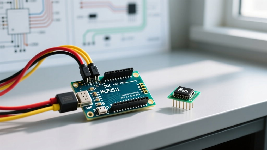

Introduction to Interfacing Arduino with CAN Bus
The Controller Area Network (CAN) bus is a robust message-based protocol designed for automotive and industrial environments where electrical noise is high and reliability is non-negotiable. While modern microcontrollers like the ESP32 or STM32 feature native CAN peripherals, the classic Arduino Uno and Nano lack this hardware. To bridge this gap, makers and engineers must interface an Arduino with CAN bus using an external SPI-to-CAN controller. The most ubiquitous and cost-effective solution in 2026 remains the Microchip MCP2515 CAN controller paired with a transceiver like the NXP TJA1050 or TI SN65HVD230.
This configuration guide moves beyond basic tutorials. We will cover the exact SPI wiring matrices, the notorious 8MHz vs. 16MHz crystal oscillator trap that causes 90% of initialization failures, proper 120-ohm network termination, and logic-level shifting requirements for modern 3.3V microcontrollers.
Hardware Bill of Materials (2026 Pricing)
Before writing code, you must assemble the physical layer. Generic clone modules are abundant, but understanding their specific silicon is critical for configuration.
- MCP2515 CAN Module (with TJA1050 Transceiver): ~$3.50 - $5.00. These modules integrate the controller, transceiver, and SPI isolation on a single PCB.
- Arduino Uno R4 Minima or Nano Every: ~$20.00 - $25.00. While the classic Uno R3 works, the R4 Minima offers a 48MHz ARM Cortex-M4, providing significantly more overhead for parsing high-throughput 500kbps CAN frames without dropping packets.
- 120-Ohm Termination Resistors (1/4W): ~$0.10 each. Mandatory for bus reflection prevention.
- Logic Level Converter (Bi-directional): ~$2.00. Required if you are adapting this setup to a 3.3V Arduino (like the Nano 33 IoT) because the TJA1050 transceiver strictly requires 5V logic and power.
- Twisted Pair Wire (CAT5e or shielded): Essential for maintaining signal integrity on the CAN_H and CAN_L differential lines.
SPI Wiring and Pinout Matrix
The MCP2515 communicates with the Arduino via the Serial Peripheral Interface (SPI). Because the Arduino Uno utilizes the ATmega328P, the hardware SPI pins are fixed. Do not attempt to use software (bit-banged) SPI for CAN bus; the timing jitter will result in corrupted frames under heavy bus loads.
| MCP2515 Module Pin | Arduino Uno / Nano Pin | Function & Configuration Notes |
|---|---|---|
| VCC | 5V | Must be a stable 5V supply. The TJA1050 transceiver will not operate on 3.3V. |
| GND | GND | Common ground is mandatory. Ensure thick gauge wire to prevent ground loops. |
| CS (Chip Select) | D10 (Pin 10) | Configurable in software, but D10 is standard for hardware SS on ATmega328P. |
| SO (MISO) | D12 (Pin 12) | Master In, Slave Out. Fixed hardware SPI pin. |
| SI (MOSI) | D11 (Pin 11) | Master Out, Slave In. Fixed hardware SPI pin. |
| SCK (Clock) | D13 (Pin 13) | SPI Clock. Fixed hardware SPI pin. |
| INT (Interrupt) | D2 (Pin 2) | Active-low interrupt. Connect to a hardware interrupt pin to avoid polling overhead. |
For deeper electrical characteristics and SPI timing diagrams, refer to the official Microchip MCP2515 Datasheet.
The 8MHz vs. 16MHz Crystal Oscillator Trap
Critical E-E-A-T Warning: The single most common reason an Arduino with CAN bus configuration fails to initialize (returning
MCP2515_ERROR_FAILINIT) is a mismatch between the physical crystal oscillator on the module and the software configuration.
Almost all inexpensive MCP2515 modules manufactured in Shenzhen feature an 8MHz crystal oscillator printed on the metal casing. However, the default examples in popular libraries like autowp-mcp2515 or Seeed-Studio CAN_BUS_Shield are hardcoded to expect a 16MHz crystal.
If your code tells the MCP2515 it is running at 16MHz, but it is actually running at 8MHz, the internal baud rate generator will calculate the bit timings incorrectly. Your Arduino will transmit at exactly half the intended baud rate (e.g., 250kbps instead of 500kbps), causing immediate acknowledgment errors from all other nodes on the network.
The Fix: Always explicitly define the clock speed in your initialization code:
// Correct configuration for standard cheap modules
mcp2515.setBitrate(CAN_500KBPS, MCP_8MHZ);
Network Termination: The 120-Ohm Rule
CAN bus relies on differential signaling. According to the ISO 11898 standard, the physical layer requires a nominal 120-ohm termination resistor at both extreme ends of the bus topology to prevent signal reflections. You can read more about the physical layer requirements in the Texas Instruments CAN Physical Layer Guide.
- Two-Node Network: If you are only testing with two Arduinos, both MCP2515 modules must have their 120-ohm termination jumpers closed (or resistors soldered).
- Multi-Node Network: If you are tapping into an existing automotive OBD-II port or a long industrial run, the network already has termination. You must remove the 120-ohm jumper on your Arduino's MCP2515 module to avoid dragging the bus impedance down to 60 ohms or lower, which will cause transceiver overheating and dominant-bit clamping.
Logic Level Shifting for 3.3V Microcontrollers
While the classic Arduino Uno operates at 5V, modern makers frequently use the Arduino Nano 33 IoT, ESP32, or Raspberry Pi Pico. The TJA1050 transceiver found on most MCP2515 breakout boards requires a 5V supply and 5V logic thresholds on the TX/RX lines.
Feeding 5V from the TJA1050's TX pin directly into a 3.3V ESP32 GPIO will degrade the silicon over time and may cause immediate latch-up. If you are building a 3.3V system, you have two options:
- Use a Bi-directional Logic Level Shifter: Place a MOSFET-based level shifter (like the BSS138) between the MCP2515 module's SPI lines and the 3.3V microcontroller.
- Swap the Transceiver: Desolder the TJA1050 and replace it with a TI SN65HVD230 or NXP TJA1042. These transceivers operate natively at 3.3V and interface directly with modern low-voltage microcontrollers without level shifting.
Software Configuration and Code Implementation
For this guide, we utilize the highly optimized autowp-mcp2515 library, available via the Arduino Library Manager. It correctly handles the SPI buffer limits of the ATmega328P.
Below is a robust transmitter sketch configured for a standard 500kbps automotive network.
#include <SPI.h>
#include <mcp2515.h>

// Define CS pin
#define CAN_CS_PIN 10

struct can_frame canMsg;
MCP2515 mcp2515(CAN_CS_PIN);

void setup() {
  Serial.begin(115200);
  SPI.begin();

  mcp2515.reset();

  // CRITICAL: Match the physical crystal on your board (usually 8MHz)
  if (mcp2515.setBitrate(CAN_500KBPS, MCP_8MHZ) == MCP2515_OK) {
    Serial.println("CAN Bus Initialized Successfully at 500kbps");
  } else {
    Serial.println("Error Initializing CAN Bus - Check Wiring & Crystal");
    while(1); // Halt execution
  }

  mcp2515.setNormalMode();
}

void loop() {
  // Prepare CAN Frame
  canMsg.can_id  = 0x0F6; // Standard 11-bit ID
  canMsg.can_dlc = 8;     // Data Length Code
  canMsg.data[0] = 0x8E;
  canMsg.data[1] = 0x87;
  canMsg.data[2] = 0x32;
  canMsg.data[3] = 0xFA;
  canMsg.data[4] = 0x26;
  canMsg.data[5] = 0x8E;
  canMsg.data[6] = 0xBE;
  canMsg.data[7] = 0x86;

  // Transmit
  byte sndStat = mcp2515.sendMessage(&canMsg);
  if (sndStat == MCP2515_OK) {
    Serial.println("Message Sent");
  } else {
    Serial.println("Error Sending Message");
  }

  delay(100);
}
For comprehensive details on SPI bus management and clock dividers, consult the Arduino SPI Reference.
Diagnostic Troubleshooting Matrix
When your Arduino with CAN bus setup fails, use this matrix to isolate the physical or logical fault.
| Symptom / Serial Output | Root Cause | Actionable Fix |
|---|---|---|
MCP2515_ERROR_FAILINIT |
SPI communication failure or wrong CS pin. | Verify D10-D13 wiring. Ensure VCC is exactly 5V. Check for cold solder joints on the SPI header. |
MCP2515_ERROR_FAILTX |
Bus is in error-passive state or no ACK received. | Check 120-ohm termination. Verify baud rate matches the target network. Ensure CAN_H and CAN_L are not swapped. |
| Messages send, but receiver reads garbage data. | Crystal oscillator mismatch (8MHz vs 16MHz). | Inspect the silver oscillator on the MCP2515 board. Update setBitrate() to match the printed value. |
| Transceiver IC gets physically hot to the touch. | Bus impedance too low (too many termination resistors). | Measure resistance between CAN_H and CAN_L with a multimeter. It must read ~60 ohms. Remove extra 120-ohm jumpers. |
Summary
Successfully configuring an Arduino with CAN bus requires strict attention to physical layer details. By ensuring proper SPI wiring, explicitly defining the 8MHz crystal oscillator in software, and managing 120-ohm network termination, you can build industrial-grade telemetry nodes capable of surviving harsh electrical environments. Always verify your transceiver logic levels before connecting modern 3.3V microcontrollers to legacy 5V CAN modules.