
The Reality of Arduino Audio: Why Your Earphone Jack Sounds Terrible
Connecting a standard 3.5mm earphone jack to an Arduino Uno or Nano is a rite of passage for makers building custom audio players, synthesizers, or alarm systems. However, the result is often a deafening high-pitched whine, muffled output, or complete silence. The root cause almost always traces back to a fundamental misunderstanding of how microcontrollers generate audio and the physical realities of audio impedance.
Unlike dedicated audio processors, standard 8-bit AVR microcontrollers (like the ATmega328P found on the Uno and Nano) do not have a built-in Digital-to-Analog Converter (DAC). Instead, they simulate analog audio using Pulse Width Modulation (PWM). When you wire a raw PWM pin directly to an earphone jack, you are feeding a high-frequency digital square wave into a low-impedance analog transducer. This guide will walk you through the exact hardware and software fixes required to turn that harsh digital noise into clean, usable audio.
Step-by-Step Troubleshooting Matrix
Before desoldering your project, diagnose your specific symptom using this troubleshooting matrix. These are the most common failure modes when wiring an earphone jack to an Arduino.
| Symptom | Probable Cause | Hardware Fix | Software Fix |
|---|---|---|---|
| Loud, high-pitched whine or hiss | Raw PWM carrier frequency (490Hz or 980Hz) hitting the speaker coil. | Install an RC Low-Pass Filter between the MCU pin and the jack. | Change Timer registers to push PWM frequency above 20kHz (ultrasonic). |
| Muffled audio or no sound at all | Missing DC blocking capacitor or shorted voice coil. | Add a 10µF to 100µF series capacitor to block DC offset. | Verify WAV file format (must be 8-bit, 16kHz, Mono). |
| Audio only plays in one earbud | TRS vs TRRS mismatch; mono signal not bridged to stereo channels. | Bridge the Tip and Ring1 pins on the 3.5mm jack. | N/A (Hardware routing issue). |
| Severe distortion or clipping | Impedance mismatch. Earphones (16-32Ω) draw too much current from the ATmega pin. | Add an op-amp buffer or an audio amplifier IC (e.g., LM386). | Reduce software volume scaling to prevent digital clipping. |
The Hardware Fix: Designing the RC Low-Pass Filter
The most critical step in any earphone jack Arduino project is smoothing the PWM square wave into a pseudo-analog sine wave. If you skip this, the 32-ohm impedance of standard earphones will act as an antenna for the PWM switching noise.
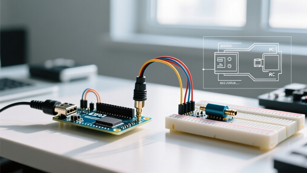
To fix this, you must build a first-order RC (Resistor-Capacitor) low-pass filter. The goal is to set the cutoff frequency just above the highest audio frequency you intend to play, but well below the PWM carrier frequency.
Calculating the Filter Components
For standard 8-bit Arduino audio (usually capped at 8kHz to 16kHz sample rates), a cutoff frequency of around 15.9kHz is ideal. Using the standard cutoff formula fc = 1 / (2 * π * R * C):
- Resistor (R): 1kΩ
- Capacitor (C): 10nF (0.01µF) ceramic capacitor
This combination effectively bleeds the high-frequency PWM carrier to ground while allowing the audio envelope to pass through to the earphone jack's TIP pin.
The Mandatory DC Blocking Capacitor
PWM signals on an Arduino oscillate between 0V and 5V, meaning they carry a 2.5V DC offset. If you feed this directly into an earphone jack, the DC current will constantly bias the speaker coil, causing overheating, reduced dynamic range, and a loud 'pop' when the circuit is powered on or off.
Expert Warning: Always place a DC blocking capacitor in series with the audio signal path. A 47µF or 100µF electrolytic capacitor is standard. Ensure the positive leg faces the Arduino RC filter and the negative leg faces the earphone jack TIP. Using a non-polarized film capacitor (like a 10µF WIMA) will yield superior audio fidelity by eliminating electrolytic distortion, though they are physically larger and more expensive.
The TRRS Trap: Smartphone Jack Pinout Nightmares
Many makers salvage 3.5mm jacks from old smartphones or buy cheap breakout boards online, only to find the audio is completely dead. This is usually due to the TRRS (Tip, Ring, Ring, Sleeve) standard used for headsets with built-in microphones.
Modern smartphones use the CTIA standard for TRRS jacks. The pinout from tip to sleeve is:
- Tip: Left Audio
- Ring 1: Right Audio
- Ring 2: Ground
- Sleeve: Microphone
If you mistakenly wire your Arduino ground to the Sleeve (thinking it's a standard TRS stereo jack), you are actually routing ground through the microphone bias circuit, effectively shorting your audio signal. The Fix: Use a multimeter in continuity mode. Insert a known TRS stereo plug into the jack and test which pins connect to the Left, Right, and Ground channels. Always wire your Arduino ground to the Ring 2 pin on CTIA TRRS jacks.
Software Optimization: Pushing PWM Beyond Human Hearing
By default, Arduino pins 9 and 10 operate at a PWM frequency of roughly 490Hz. This is well within the human hearing range (20Hz - 20kHz), which is why raw PWM sounds like a harsh, buzzing tone. To fix this, we use Timer 1 (which controls pins 9 and 10 on the Uno/Nano) and manipulate the registers to push the frequency to 31.25kHz—safely above human hearing.
Add this code to your setup() function before initializing your audio library:
void setup() {
  pinMode(9, OUTPUT);
  // Configure Timer 1 for Phase and Frequency Correct PWM
  // Prescaler = 1 (16MHz), ICR1 = 255 for 8-bit resolution
  // Resulting frequency: ~31.25 kHz
  TCCR1A = _BV(COM1A1) | _BV(WGM11);
  TCCR1B = _BV(WGM13) | _BV(WGM12) | _BV(CS10);
  ICR1 = 255;
}
According to the official Arduino PWM documentation, manipulating Timer 1 in this way sacrifices the use of the Servo library, but it drastically reduces audible PWM whine when paired with the RC filter mentioned above.
Managing Audio Files with TMRpcm
When using an SD card module to play audio through an earphone jack, the TMRpcm library remains the gold standard for AVR boards. However, the most common reason for 'silent' playback is improper WAV file formatting. The ATmega328P lacks the RAM and processing speed to decode MP3s or handle 44.1kHz stereo audio.
Strict WAV Requirements for TMRpcm:
- Format: PCM Unsigned 8-bit
- Sample Rate: 16,000 Hz (16kHz)
- Channels: Mono (1 channel)
Use a free tool like Audacity to export your audio files. Go to File > Export > Export as WAV, and ensure the encoding is set to 'Unsigned 8-bit PCM'. If your file is 16-bit or stereo, the Arduino will either play it at half-speed with demonic distortion, or fail to read the header entirely.
Detecting Earphone Plug Insertion (Switching Jacks)
A common requirement in portable Arduino projects is detecting when a user plugs in headphones to mute an external speaker. Many 3.5mm panel-mount jacks feature a 5th pin called the 'Switch' or 'Detect' pin.
Internally, this pin is connected to the Sleeve (Ground) when no plug is inserted. When a plug is pushed in, the physical connection breaks. To use this in your sketch:
- Wire the Switch pin to Arduino Digital Pin 2.
- Wire the Sleeve pin to Arduino GND.
- Use the internal pull-up resistor in your code:
pinMode(2, INPUT_PULLUP);
When the jack is empty, the pin reads LOW (pulled to ground). When the earphone is inserted, the circuit opens, and the internal pull-up drives the pin HIGH. This provides a clean, debounce-free hardware interrupt trigger for your audio routing logic.
The 2026 Alternative: Bypassing PWM with I2S DACs
While fixing PWM audio is an excellent learning exercise, the maker ecosystem in 2026 heavily favors dedicated I2S DACs for any project requiring high-fidelity earphone jack output. If you are using a 32-bit board like the ESP32 or Raspberry Pi Pico, you have access to hardware I2S protocols.
Modules based on the MAX98357A or PCM5102A chips cost between $4 and $8. They take digital I2S data directly from the microcontroller and perform high-resolution 24-bit digital-to-analog conversion onboard. As detailed in Adafruit's I2S amplifier guide, this completely eliminates the need for RC filters, DC blocking capacitors, and Timer register hacks, delivering CD-quality audio directly to your 3.5mm jack with zero PWM hiss.
Summary Checklist for Clean Audio
If your earphone jack Arduino project is failing, verify these four pillars:
- Is the PWM frequency pushed above 20kHz via Timer registers?
- Is a 1kΩ / 10nF RC filter installed to smooth the square wave?
- Is a 47µF DC blocking capacitor protecting the earphone coil?
- Are your WAV files strictly 8-bit, 16kHz, Mono?
Mastering these hardware and software constraints will transform your microcontroller from a noisy digital switcher into a reliable, custom audio engine.