
The Critical Role of Current Limiting in MCU Circuits
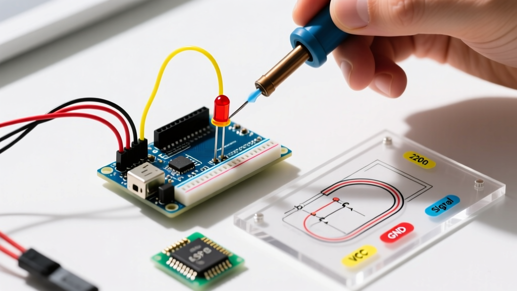
Connecting an LED directly to an Arduino GPIO pin without a current-limiting resistor is one of the most common mistakes beginners make. While it might light up brightly for a few seconds, it forces the microcontroller's I/O pin to supply far more current than it is rated for. The ATmega328P chip (found in the Arduino Uno and Nano) has an absolute maximum rating of 40mA per pin and a recommended operating current of 20mA. Exceeding this degrades the silicon over time, eventually leading to dead pins or a completely fried microcontroller.
This quick reference guide and FAQ will give you the exact resistor for LED Arduino calculations, standard values, and edge-case troubleshooting you need to build reliable circuits in 2026.
Pro-Tip: Always round up to the nearest standard E12 or E24 resistor value. A slightly higher resistance reduces current, which dims the LED marginally but drastically increases the lifespan of both the LED and your Arduino.
Quick Reference Table: Standard Resistor Values
Most standard 5mm through-hole LEDs (like the popular Kingbright WP710 series) operate at a forward current (If) of 20mA. Below is a cheat sheet for 5V boards (Uno, Mega, Leonardo) and 3.3V boards (Nano 33 IoT, Due, ESP32).
| LED Color | Typical Forward Voltage (Vf) | 5V Board Resistor (Target 20mA) | 3.3V Board Resistor (Target 20mA) |
|---|---|---|---|
| Infrared (IR) | 1.2V | 200Ω (190Ω calculated) | 110Ω (105Ω calculated) |
| Red | 2.0V | 150Ω | 68Ω (65Ω calculated) |
| Yellow / Orange | 2.1V | 150Ω (145Ω calculated) | 62Ω (60Ω calculated) |
| Green (Standard) | 2.2V | 150Ω (140Ω calculated) | 56Ω (55Ω calculated) |
| Blue / Pure Green | 3.2V | 100Ω (90Ω calculated) | 10Ω (5Ω calculated) |
| White / UV | 3.3V | 100Ω (85Ω calculated) | Not recommended on 3.3V* |
*Note: For 3.3V logic boards driving White or Blue LEDs (Vf 3.2V-3.3V), the voltage headroom is too small for a reliable resistor calculation. Use a transistor driver or a boost converter instead.
How to Calculate the Exact Resistor Value
If you are using a specialized LED (such as a high-power Cree C503B or a specific surface-mount 0805 LED), you must calculate the resistor using Ohm's Law. The All About Circuits LED Calculator is a great digital tool, but knowing the manual formula is essential for field troubleshooting.
The Formula
R = (V_source - V_forward) / I_forward
- V_source: The voltage of your Arduino pin (5V or 3.3V).
- V_forward (Vf): Found on the LED's datasheet (e.g., 2.0V for Red).
- I_forward (If): The desired current in Amps. For standard indicators, 15mA (0.015A) is usually bright enough and safer for the MCU than the full 20mA.
Example Calculation
You have a 5V Arduino Uno and a Yellow LED (Vf = 2.1V). You want to run it at a safe 15mA (0.015A) to conserve power in a battery-operated project.
- R = (5.0 - 2.1) / 0.015
- R = 2.9 / 0.015
- R = 193.33Ω
Since 193Ω is not a standard value, you round up to the nearest E12 series value: 200Ω or 220Ω. Both will work perfectly, with 220Ω being the most ubiquitous value in maker kits.
Power Rating and Tolerance: What to Buy
When ordering resistors (typically $12 to $18 for a 1000-piece E12 metal film kit on Amazon or Mouser in 2026), you must select the correct wattage and tolerance.
Wattage (Power Dissipation)
Resistors convert excess voltage into heat. You must ensure your resistor can handle the power load without burning up. The formula is P = I² × R.
Using our previous example (15mA through a 200Ω resistor):
- P = (0.015)² × 200
- P = 0.000225 × 200 = 0.045 Watts
A standard 1/4W (0.25W) or even 1/8W (0.125W) through-hole resistor is more than sufficient, providing a massive safety margin. You only need 1/2W or 1W resistors if you are driving high-power 1W or 3W Star LEDs directly, which is generally not recommended without a dedicated constant-current LED driver.
Tolerance
For basic indicator LEDs, a 5% tolerance (gold band) is perfectly fine. If a 220Ω resistor is actually 230Ω, the LED will be imperceptibly dimmer. For precision optical sensing or multiplexed displays, opt for 1% tolerance (metal film, brown band) to ensure uniform brightness across all pixels.
Frequently Asked Questions (FAQ)
Can I just use a 220-ohm or 330-ohm resistor for everything?
Yes, for basic prototyping on 5V Arduino boards, a 220Ω or 330Ω resistor is the universal 'safe bet' for standard Red, Yellow, Green, and Blue 5mm LEDs. It limits the current to between 10mA and 15mA, which is well within the Arduino Digital Pin specifications and provides ample brightness for indoor indicators. However, for 3.3V boards, 330Ω will make Red LEDs very dim; use 68Ω or 100Ω instead.
Does the resistor go on the Anode (+) or Cathode (-)?
Electrically, it does not matter. Because the LED and resistor form a single series circuit, the current is identical at all points in the loop. However, standard industry practice and SparkFun's LED wiring guides recommend placing the resistor on the Anode (positive/long leg) side. This makes troubleshooting with a multimeter easier and prevents accidental short circuits if the exposed cathode leg touches a grounded chassis.
What happens if I connect an LED without a resistor?
The LED will attempt to draw as much current as the power supply can provide. Because the LED's forward voltage (e.g., 2.0V) is lower than the Arduino's output (5.0V), the remaining 3.0V is pushed across the internal resistance of the ATmega328P's silicon pathways. This causes rapid thermal runaway inside the microcontroller. The pin may survive for a few minutes, but it will suffer permanent electromigration damage, eventually failing to output HIGH or LOW signals.
Do Addressable LEDs (WS2812B / NeoPixels) need resistors?
The individual WS2812B LEDs contain internal constant-current driver ICs, so you do not need current-limiting resistors for the power lines (VCC/GND). However, Adafruit and other manufacturers highly recommend placing a 300Ω to 470Ω resistor directly on the Data In (DIN) line, as close to the first pixel as possible. This is not for current limiting; it acts as a termination resistor to dampen high-frequency signal reflections and protect the first pixel's data logic gate from voltage spikes during hot-plugging.
Advanced Edge Cases: Multiplexing and Shift Registers
If you are driving multiple LEDs using a shift register like the 74HC595 or a transistor array like the ULN2803, the rules change slightly.
- 74HC595: The entire chip can only handle about 70mA total continuous current. If you are lighting 8 Red LEDs simultaneously, you must limit each LED to roughly 8mA. Recalculate your resistor: R = (5V - 2V) / 0.008A = 375Ω. Use 390Ω or 470Ω resistors to prevent frying the shift register.
- Charlieplexing: Because LEDs are only lit for a fraction of a second (duty cycle), you can safely push higher peak currents (up to the 40mA absolute max) to maintain perceived brightness. A 100Ω resistor is common for charlieplexed 5V arrays, but ensure your software includes a failsafe to prevent a frozen loop from keeping a single pin HIGH indefinitely.
Summary Checklist for Your Next Build
- Identify your board logic level (5V vs 3.3V).
- Check the LED datasheet for Vf and max If.
- Calculate R using Ohm's law, targeting 15mA for longevity.
- Round up to the nearest E12 standard value.
- Verify the resistor wattage (1/4W is standard).
- Place the resistor on the Anode side for clean breadboarding.