
The Architecture of Arduino DMX Control
Integrating microcontrollers into stage lighting and interactive art installations requires a robust understanding of the DMX512-A protocol. Originally defined by the US Institute for Theatre Technology (USITT) and later standardized as ANSI E1.11 by the Entertainment Services and Technology Association (ESTA), DMX512 relies on an RS-485 differential signaling physical layer. While modern networks often use sACN (Streaming ACN) or Art-Net over Ethernet, raw DMX512 remains the undisputed standard for direct fixture control at the edge. Configuring an Arduino DMX controller is not as simple as toggling a digital pin; it requires precise hardware serial timing, differential voltage management, and strict adherence to framing protocols. This configuration guide details the exact hardware selection, wiring schematics, and software initialization required to build a reliable, flicker-free DMX master node in 2026.
Hardware Bill of Materials (BOM) & Component Selection
To build a professional-grade DMX transmitter, you must move beyond basic breadboard prototypes and address the electrically noisy environments typical of stage and event production. Below is the recommended BOM with current market pricing.
- Microcontroller: Arduino Mega 2560 ($18 clone / $48 genuine). We strongly advise against using the Arduino Uno R3 or R4 Minima for multi-channel DMX. The Mega 2560 features four hardware UARTs, allowing you to dedicate Serial1 to DMX transmission while keeping Serial0 (USB) free for real-time debugging.
- RS-485 Transceiver Module: Optically Isolated RS-485 Module featuring the MAX485 or SP485 chip ($9 - $14). Standard non-isolated MAX485 breakout boards ($2) are acceptable for bench testing but pose a severe risk of ground-loop destruction in live environments.
- Connectors: Neutrik NC5FAV 5-pin XLR Female Panel Receptacle ($6.50). While 3-pin XLR is common in budget LED pars, 5-pin is the ANSI standard.
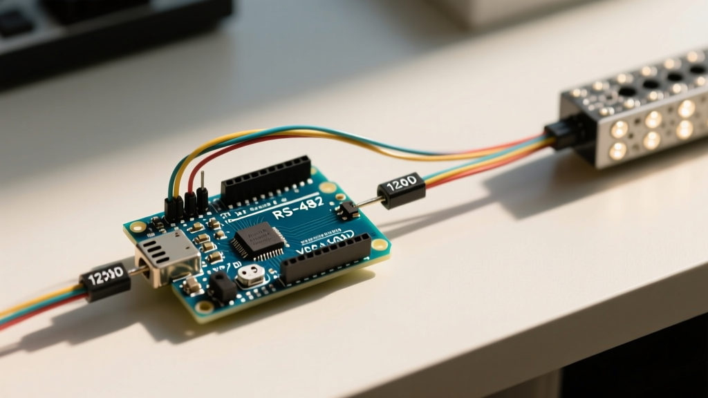
- Termination Resistor: 120-ohm, 1/4W metal film resistor ($0.15).
- Cabling: 110-ohm impedance DMX cable (e.g., Belden 9841). Do not use standard analog microphone cable, as its higher capacitance will degrade the 250 kbps square wave signal over long runs.
Why Isolation is Non-Negotiable in Live Environments
Stage lighting grids are notorious for severe ground potential differences. If your Arduino shares a common ground with a moving head fixture via the XLR shield, a fault in the fixture's power supply can send 120V AC straight through the RS-485 transceiver and into your microcontroller's 5V rail, instantly vaporizing the ATmega2560. An optically isolated RS-485 module uses high-speed optocouplers (like the 6N137) and an isolated DC-DC converter to break the galvanic connection, protecting your logic circuits while maintaining the differential signal integrity.
Step-by-Step Wiring: Isolated RS-485 to XLR
Proper wiring of the RS-485 differential pair is critical. The DMX512 standard specifies that Pin 2 is Data 1- (Inverting) and Pin 3 is Data 1+ (Non-inverting). Reversing these will result in inverted logic, causing fixtures to behave erratically or ignore the signal entirely.
| Arduino Mega 2560 Pin | Isolated RS-485 Module Pin | XLR 5-Pin Female Pin | Function / Notes |
|---|---|---|---|
| 5V (or VCC) | VCC | - | Powers the isolated logic side. |
| GND | GND | - | Logic ground (Do NOT connect to XLR Pin 1). |
| TX1 (Pin 18) | TXD / DI | - | Hardware Serial 1 Data Transmit. |
| - | VCC (Jumpered to DE/RE) | - | Hardwire DE and RE HIGH for TX-only mode. |
| - | A (Non-Inverting) | Pin 3 (Data 1+) | Positive differential signal line. |
| - | B (Inverting) | Pin 2 (Data 1-) | Negative differential signal line. |
| - | - | Pin 1 (Shield/Common) | Connect to XLR shell / Cable shield. |
Pro-Tip on Termination: The DMX512 standard requires a 120-ohm termination resistor across Pin 2 and Pin 3 at the physical end of the daisy chain to prevent signal reflection. Do not build this resistor into your Arduino DMX shield; it must be placed at the final fixture or use a dedicated XLR termination plug. According to the Texas Instruments RS-485 Design Guide, missing termination on cables longer than 10 meters will cause severe ringing at the 250 kbps baud rate, leading to intermittent fixture dropouts.
DMX512-A Timing and Framing Specifications
Unlike standard serial communication, DMX512 requires a specific "Break" and "Mark After Break" (MAB) sequence to signal the start of a new universe packet. The Arduino's standard Serial.begin() function does not natively generate a break condition. You must use a library that manipulates the USART registers directly to force the TX line LOW for the required duration.
Protocol Timing Matrix
| Parameter | Minimum | Recommended | Maximum |
|---|---|---|---|
| Break Time | 88 µs | 120 µs - 176 µs | 1 sec |
| Mark After Break (MAB) | 8 µs | 12 µs | 1 sec |
| Baud Rate | 250,000 bps (Strict) | ||
| Data Format | 8 Data Bits, No Parity, 2 Stop Bits (8N2) | ||
Software Configuration: Conceptinetics Library
For the Arduino Mega 2560, the Conceptinetics library remains the most robust solution for hardware-serial DMX transmission. It correctly handles the Break and MAB timing by utilizing the USART control registers. For deeper insights into how hardware serial buffers operate under the hood, refer to the official Arduino Serial Reference.
Below is the production-ready configuration code to initialize a 512-channel DMX universe on Serial1 (TX Pin 18).
#include <Conceptinetics.h>

// Define the DMX Master on Serial1 (Pin 18 on Mega)
// The library handles the Break and MAB timing automatically
DMX_Master dmx_master(512, 18);

void setup() {
  // Initialize standard serial for debugging on Serial0 (USB)
  Serial.begin(115200);

  // Enable the DMX Master and set to transmit mode
  dmx_master.enable();

  // Set all 512 channels to 0 (Blackout) on startup
  dmx_master.setChannelRange(1, 512, 0);

  Serial.println("Arduino DMX Node Initialized.");
}

void loop() {
  // Example: Fade Channel 1 (Dimmer) from 0 to 255
  for (int i = 0; i <= 255; i++) {
    dmx_master.setChannelValue(1, i);
    delay(20); // 20ms delay for smooth fade
  }

  // Example: Set Channel 5 (Color Macro) to 128
  dmx_master.setChannelValue(5, 128);

  delay(1000); // Hold scene for 1 second
}
Advanced Troubleshooting: Edge Cases and Failures
Even with perfect wiring, DMX networks in the field present unique failure modes. Here is how to diagnose the most common issues encountered when deploying Arduino DMX controllers.
1. The "Ghost Channel" Flicker
Symptom: Fixtures randomly strobe, or channels at the end of the universe (e.g., channels 450-512) flicker intermittently.
Root Cause: This is almost always a timing violation. If the Break time is too short (under 88µs), receivers may mistake the break for a standard data byte, causing the entire packet to shift by one byte. Alternatively, if your code introduces massive blocking delays (e.g., delay(5000)) inside the loop(), the library may fail to refresh the DMX packet within the receiver's timeout window (typically 2 seconds), causing the fixture to enter a fail-safe or hold mode.
Solution: Ensure your loop() executes rapidly. Use non-blocking timing methods like millis() for scene transitions to guarantee the Conceptinetics library can continuously stream the 44Hz refresh rate required by the protocol.
2. Ground Loop MCU Destruction
Symptom: The Arduino randomly resets, the onboard voltage regulator becomes too hot to touch, or the MCU is permanently dead.
Root Cause: You connected the Arduino's logic GND to XLR Pin 1 (Signal Common) while using a non-isolated MAX485 module. Stage lighting dimmers and LED drivers inject massive amounts of common-mode noise into the ground plane. This noise travels back up the XLR shield, through your breakout board, and into the Arduino's ground, creating a ground loop that overwhelms the linear voltage regulator.
Solution: Never connect Arduino GND to XLR Pin 1 unless you are using a fully isolated RS-485 transceiver module with an integrated isolated power supply. Leave XLR Pin 1 floating on the Arduino side, or connect it strictly to the cable shield via a high-value resistor and capacitor network for EMI shielding without creating a DC ground path.
3. RDM (Remote Device Management) Collisions
Symptom: You attempt to implement bidirectional RDM to discover fixture UIDs, but the bus locks up.
Root Cause: Standard DMX is unidirectional. RDM requires the transceiver to switch the DE/RE pins to listen for responses from the fixtures during specific time slots. If your code does not precisely manage the turnaround time (the time between the end of the DMX packet and the start of the RDM response window), data collisions will occur.
Solution: For 95% of maker projects, raw DMX transmission is sufficient. If RDM is strictly required, abandon the Mega 2560 and migrate to a Teensy 4.1 using the TeensyDmx library, which utilizes the Teensy's advanced hardware timers to manage microsecond-accurate bus turnaround without blocking the main CPU.
Summary
Building a reliable Arduino DMX interface requires respecting both the electrical realities of RS-485 differential signaling and the strict timing constraints of the ANSI E1.11 standard. By utilizing an Arduino Mega 2560 for dedicated hardware UARTs, investing in optically isolated transceivers to survive stage ground loops, and leveraging the Conceptinetics library for accurate Break/MAB framing, you can deploy microcontroller-driven lighting installations that rival commercial consoles in stability and performance.