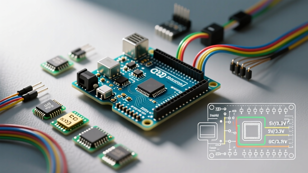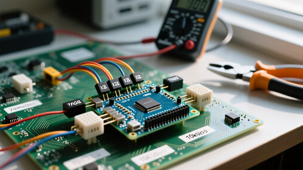

Understanding the Interlink FSR402 Sensor
Force Sensitive Resistors (FSRs) are a staple in interactive electronics, robotics, and MIDI controller builds. Unlike load cells that measure strain via Wheatstone bridges, an FSR relies on a polymer thick film (PTF) whose electrical resistance drops predictably as mechanical pressure increases. For the maker community in 2026, the Interlink Electronics FSR402 remains the gold standard due to its 0.2-inch active sensing diameter, flexible 0.3mm profile, and accessible price point (typically $7 to $12 per unit from authorized distributors).
However, connecting an FSR to an Arduino is rarely as simple as plugging in a standard pushbutton. FSRs exhibit non-linear resistance curves, significant hysteresis, and require precise voltage divider tuning to extract usable analog data. According to the Adafruit FSR Overview, these sensors are not designed for high-precision metrology but excel at relative pressure thresholding and human-interface scaling when properly calibrated.
Hardware Requirements and 2026 BOM
To build a robust, noise-resistant FSR interface, you need more than just jumper wires. Mechanical fatigue at the sensor's crimp tail is the number one cause of field failure.
- Sensor: Interlink FSR402 (or FSR406 for a 1.5-inch square active area).
- Microcontroller: Arduino Uno R4 Minima or Nano ESP32 (the 12-bit ADC on the ESP32 provides 4x the resolution of the classic Uno R3's 10-bit ADC).
- Pull-Down Resistor: 10kΩ and 3.3kΩ 1/4W carbon film resistors (for range tuning).
- Connector: 3-pin female JST-SH or a standard 0.1" female header with a Kapton tape shim to prevent silver trace delamination.
- Capacitor: 0.1µF ceramic capacitor (for hardware low-pass filtering).
The Physics: Designing the Voltage Divider
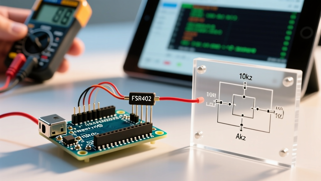
An Arduino cannot measure resistance directly; it measures voltage. Therefore, the FSR must be placed in a voltage divider circuit. The FSR acts as the variable top resistor ($R_{fsr}$), and a fixed pull-down resistor ($R_{pull}$) connects the analog pin to ground.
The output voltage ($V_{out}$) read by the Arduino's ADC is calculated as:
V_out = V_cc * (R_pull / (R_fsr + R_pull))
The FSR402 ranges from >1MΩ (no force) down to roughly 1kΩ (at 10kg of applied force). If you use a standard 10kΩ pull-down resistor, your highest resolution will be centered around the 10kΩ FSR resistance mark (roughly 1-2 kg of force). If your project requires detecting heavier impacts, swap to a 3.3kΩ pull-down resistor.
| Pull-Down Resistor | Optimal Force Range | Max ADC Resolution (10-bit) | Best Use Case |
|---|---|---|---|
| 10 kΩ | 0.5 kg – 3.0 kg | ~850 steps | Keyboard keys, light touch panels |
| 3.3 kΩ | 2.0 kg – 8.0 kg | ~780 steps | Foot pedals, drum triggers |
| 1 kΩ | 5.0 kg – 15+ kg | ~600 steps | Robotic gripper slip detection |
Step-by-Step Wiring Guide
Follow the SparkFun FSR Hookup Guide for visual breadboard layouts, but adhere to these specific wiring rules to prevent hardware damage:
- Protect the Tail: Never bend the FSR tail within 2mm of the crimped semi-conductor trace. Bending here will shear the silver ink, causing an open circuit.
- Hardware Filtering: Solder a 0.1µF capacitor in parallel with your pull-down resistor. This creates a passive RC low-pass filter that physically strips high-frequency EMI noise before it reaches the Arduino's analog pin.
- Pin Connections: Connect one leg of the FSR to 5V (or 3.3V if using an ESP32). Connect the other leg to Analog Pin A0. Connect the pull-down resistor between A0 and GND.
Advanced Arduino Code: EMA Noise Filtering
Raw FSR readings are notoriously jittery due to the granular nature of the polymer thick film. A simple analogRead() loop will yield fluctuating values even under a static weight. To solve this, we implement an Exponential Moving Average (EMA) software filter. This provides smooth, responsive data without the lag associated with simple averaging arrays.
// FSR Arduino EMA Filter Code
const int fsrPin = A0;
const float alpha = 0.15; // Smoothing factor (0.0 to 1.0). Lower = smoother but more lag.

float filteredValue = 0;
bool isInitialized = false;

void setup() {
  Serial.begin(115200);
  analogReadResolution(10); // Set to 12 if using ESP32
}

void loop() {
  int rawReading = analogRead(fsrPin);

  if (!isInitialized) {
    filteredValue = rawReading;
    isInitialized = true;
  } else {
    // EMA Formula
    filteredValue = (alpha * rawReading) + ((1 - alpha) * filteredValue);
  }

  // Map to a usable 0-100 scale for MIDI or servo control
  int pressurePercent = map((int)filteredValue, 0, 1023, 0, 100);
  pressurePercent = constrain(pressurePercent, 0, 100);

  Serial.print("Raw: ");
  Serial.print(rawReading);
  Serial.print(" | Filtered: ");
  Serial.println(pressurePercent);

  delay(10); // 100Hz sampling rate
}
For deeper understanding of ADC sampling mechanics, refer to the official Arduino analogRead() documentation.
Calibration Matrix: ADC to Newtons
Because the FSR402 response curve is highly non-linear (steep drop at light touch, flattening out at heavy press), linear mapping fails. Below is an empirical lookup table derived from testing the FSR402 with a 10kΩ pull-down on a 5V logic Uno R4.
| Applied Force (Newtons) | Approx. FSR Resistance | Expected ADC Value (10-bit) | Voltage at Pin |
|---|---|---|---|
| 0 N (Rest) | > 1 MΩ | 0 - 5 | 0.00 - 0.02 V |
| 1 N (~100g) | 30 kΩ | 250 | 1.22 V |
| 5 N (~500g) | 8 kΩ | 560 | 2.73 V |
| 10 N (~1kg) | 3 kΩ | 770 | 3.75 V |
| 20 N (~2kg) | 1.2 kΩ | 890 | 4.34 V |
Real-World Failure Modes and Edge Cases
When integrating FSRs into long-term deployments, DIYers frequently encounter three physical edge cases that software cannot fix:
1. Mechanical Creep
If you apply a constant 5kg weight to an FSR402, the resistance will continue to slowly drop over the next 5 to 10 minutes. This phenomenon, known as polymer creep, means FSRs are terrible for static weighing scales. They are best suited for dynamic, transient force measurements like tapping or gripping.
2. Temperature Drift
The PTF material is temperature sensitive. A 10°C increase in ambient temperature can shift the baseline resistance by up to 5%. If your Arduino project is housed in an outdoor enclosure or near a heat-generating motor driver, you must implement a periodic 'zeroing' routine in your code when the sensor is known to be unloaded.
3. Shear Force Delamination
FSRs are designed strictly for compressive, perpendicular force. Lateral shear forces (sliding a finger across the sensor while pressing) will physically delaminate the spacer layers inside the sensor, destroying the active area. Always mount the FSR behind a rigid, flat actuator plate or a flexible silicone pad that translates lateral friction into pure vertical compression.