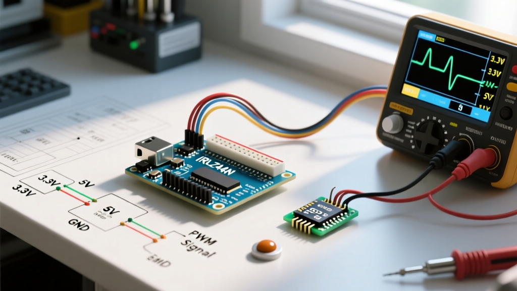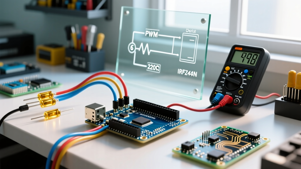

The Core Problem: Why Your Arduino Needs Transistors
If you have ever tried to power a 12V solenoid, a high-torque DC motor, or even a simple 1A LED strip directly from an ATmega328P GPIO pin, you likely learned a harsh lesson in silicon physics. Arduino digital pins are strictly limited to a maximum current of 40mA (with a recommended continuous limit of 20mA). Exceeding this threshold will permanently damage the microcontroller's internal traces. This is where the arduino transistor becomes the most critical bridge between low-voltage logic and high-power actuation.
However, navigating the sheer volume of transistor tutorials, forum debates, and conflicting wiring diagrams can be overwhelming for makers. In this 2026 community resource roundup, we synthesize the best advice from veteran electrical engineers, top-tier maker forums, and open-source hardware repositories to give you a definitive guide on selecting, calculating, and sourcing the right transistors for your MCU projects.
BJT vs. Logic-Level MOSFET: The Community Consensus
One of the most frequently debated topics on the Arduino Forum's General Electronics section is whether to use a Bipolar Junction Transistor (BJT) or a Metal-Oxide-Semiconductor Field-Effect Transistor (MOSFET). The community consensus is clear: it depends entirely on your current requirements and switching frequency.
BJTs are current-controlled devices, meaning you must continuously supply base current to keep them saturated. MOSFETs are voltage-controlled, requiring virtually zero continuous gate current, making them vastly superior for high-current loads and battery-powered IoT nodes. However, beginners frequently fall into the 'IRF520 trap'.
The Infamous IRF520 Trap
Many cheap, mass-produced 'MOSFET driver modules' sold on Amazon and AliExpress use the IRF520. While it is technically a MOSFET, it is not a logic-level MOSFET. Its Gate-Source Threshold Voltage ($V_{GS(th)}$) is rated between 2.0V and 4.0V, but it requires upwards of 10V at the gate to fully turn on and achieve its low $R_{DS(on)}$ resistance. When driven by a 5V or 3.3V Arduino pin, the IRF520 operates in its linear (ohmic) region, acting as a massive resistor that generates extreme heat and drops significant voltage to your load.
Below is a community-vetted comparison table of the most reliable transistors for Arduino switching in 2026:
| Component | Type | Max Continuous Current | Logic-Level (5V/3.3V)? | Avg. Unit Price (2026) | Best Use Case |
|---|---|---|---|---|---|
| 2N2222 | NPN BJT | 800mA | Yes | $0.04 | Small relays, low-power LEDs |
| TIP120 | Darlington BJT | 5A | Yes | $0.45 | Medium motors, 12V strips (Note: high voltage drop) |
| IRF520 | N-Channel MOSFET | 9.2A | NO | $0.80 | Avoid for 5V/3.3V MCUs |
| IRLZ44N | N-Channel MOSFET | 47A | Yes | $1.20 | High-current motors, heavy PWM dimming |
| FQP30N06L | N-Channel MOSFET | 32A | Yes | $1.05 | Through-hole alternative to IRLZ44N |
Community Pro-Tip: Always look for the 'L' in the MOSFET part number (e.g., IRLZ44N). In industry nomenclature, this often designates a 'Logic-Level' gate threshold, ensuring full saturation at 5V or lower.
Top Community Forums & Discussion Hubs
When you encounter edge cases—such as high-frequency PWM causing MOSFET gate ringing or unexpected ground loops—these are the authoritative hubs where veteran engineers provide troubleshooting support:
- EEVblog Forum (Beginners & Projects Section): Known for rigorous, no-nonsense electrical engineering advice. If you post a schematic here, expect detailed critiques on your flyback diode placement and trace width calculations.
- Arduino Forum (General Electronics): The largest repository of MCU-specific switching issues. Searching this forum for 'MOSFET gate resistor sizing' yields hundreds of real-world oscilloscope captures from community members.
- Reddit r/AskElectronics: Excellent for quick schematic reviews. The community strictly enforces the rule of 'post a schematic, not a Fritzing diagram,' which forces you to learn proper electronic symbolism.
Essential Calculator Tools & GitHub Repos
Relying on guesswork for base resistors or gate pull-downs is a recipe for burned-out GPIO pins. The community relies on several open-source tools and calculators to ensure safe operating areas (SOA).
1. Base Resistor Calculation for BJTs
To properly saturate a BJT like the 2N2222, you must calculate the exact base resistor ($R_B$). According to the All About Circuits Semiconductor Textbook, the formula is:
$R_B = \frac{V_{Pin} - V_{BE}}{I_B}$
If your Arduino outputs 5V, the base-emitter voltage drop ($V_{BE}$) is typically 0.7V. If your load requires 200mA and the transistor's $h_{FE}$ (gain) is 100, your minimum base current is 2mA. To guarantee saturation, the community standard is to overdrive the base by a factor of 2 to 5. Using a 4mA target: $R_B = (5 - 0.7) / 0.004 = 1075\Omega$. A standard 1kΩ resistor is the perfect choice here.
2. MOSFET Gate Driver Sizing
For high-frequency PWM (above 5kHz), the internal capacitance of a MOSFET gate can cause slow rise times, leading to excessive heat. The GitHub repository 'mosfet-gate-calculator' by various open-source contributors helps you calculate the required gate current to switch the MOSFET within your PWM dead-time, often revealing the need for a dedicated gate driver IC like the TC4427 if you are pushing beyond 20kHz.
The 'Inductive Load' Trap: Flyback Diode Best Practices
No community resource roundup on arduino transistor circuits is complete without addressing inductive kickback. When switching off a relay, solenoid, or DC motor, the collapsing magnetic field generates a massive reverse voltage spike (often exceeding 100V) that will instantly punch through your transistor's junction.
The Community Standard:
- Standard Relays/Solenoids: Use a 1N4007 rectifier diode placed in reverse bias across the load terminals. It costs roughly $0.02 and handles the slow decay of the magnetic field perfectly.
- High-Frequency PWM Motors: The 1N4007 is too slow to react to 20kHz PWM signals. Veteran makers strongly recommend using a Schottky diode, such as the 1N5819, which has a near-zero reverse recovery time, protecting your MOSFET from microsecond voltage spikes.
For a deeper dive into motor control physics and diode placement, SparkFun's Transistor Tutorial provides excellent visual breakdowns of current flow during the inductive collapse phase.
Recommended Starter Kits for Transistor Mastery
Instead of buying individual components, the maker community highly recommends sourcing curated assortments to build a robust lab inventory. As of 2026, here is what you should look for:
- The 'Logic-Level' MOSFET Assortment ($18 - $24): Look for kits on Amazon or DigiKey that specifically include the IRLB8721, IRLZ44N, and FQP30N06L. Avoid kits that only list 'IRF' series without the 'L'.
- Comprehensive BJT & Diode Kit ($12 - $16): A standard 500-piece kit containing 2N2222, BC547, 2N3904, and a massive assortment of 1N4148 and 1N4007 diodes. These are essential for prototyping H-bridges and logic gates.
- Pre-wired MOSFET Switch Modules ($3.50 each): If you want to skip the breadboard wiring, look for modules based on the AO3400 or IRLB8721. Ensure the product description explicitly states '3.3V/5V Logic Compatible'.
Frequently Asked Questions (FAQ)
Can I connect multiple Arduino pins to a single transistor base to get more current?
No. This is a dangerous practice that can cause current to backfeed between GPIO pins, potentially destroying the ATmega328P. If you need more base drive, use a Darlington pair or switch to a logic-level MOSFET.
Do I need a pull-down resistor on a MOSFET gate?
Yes. A 10kΩ resistor between the Gate and Source (Ground) is highly recommended. It ensures the MOSFET remains firmly off during Arduino boot-up sequences when GPIO pins are floating in a high-impedance state.
Why is my TIP120 getting incredibly hot at just 2 Amps?
The TIP120 is a Darlington BJT, which inherently has a high collector-emitter saturation voltage ($V_{CE(sat)}$) of about 1.5V to 2.0V. At 2A, it is dissipating 3 to 4 Watts of heat ($P = V \times I$). You must attach a heatsink, or better yet, replace it with an IRLZ44N MOSFET which will dissipate less than 0.1W under the same conditions.