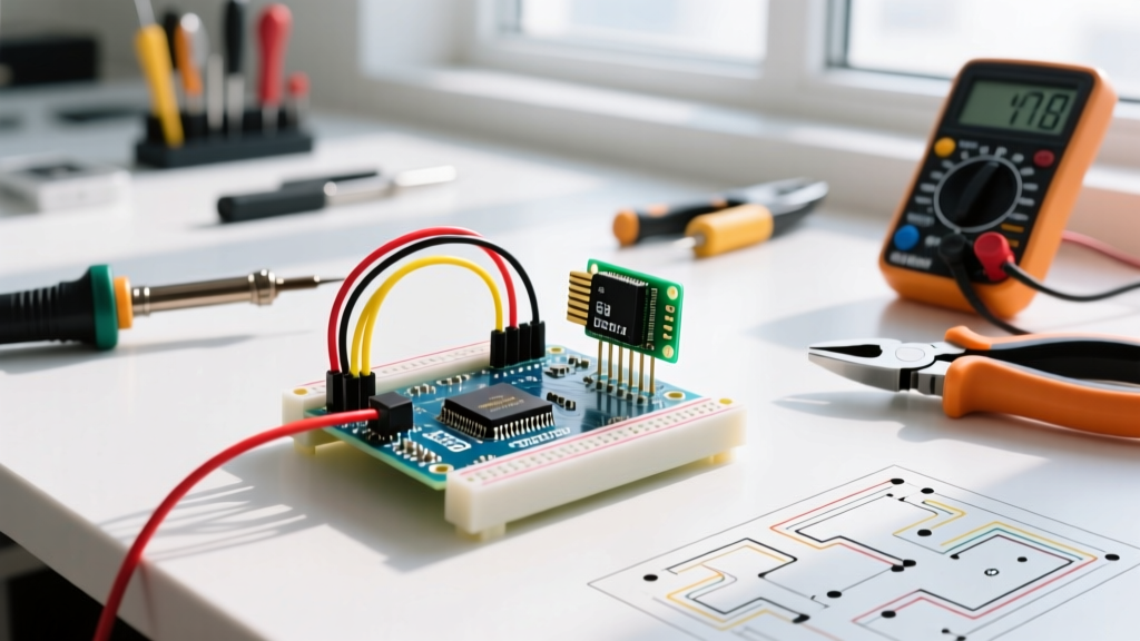

The Hardware Bottleneck: Why Direct Pin Driving Fails
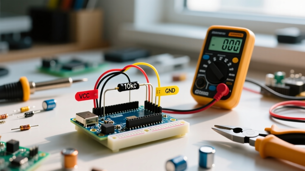
Integrating audio feedback into microcontroller projects is a fundamental skill, yet the standard approach to wiring a piezoelectric buzzer Arduino setup often leads to degraded hardware and blocked execution loops. Many makers simply connect a passive piezo directly between a digital PWM pin and ground. While this might produce a faint sound on a breadboard, it is an engineering anti-pattern that risks damaging your MCU's GPIO pins and creates severe software timing bottlenecks.
A typical piezoelectric transducer acts as a capacitive load (usually between 15nF and 30nF). When an Arduino Uno R4 or Nano ESP32 pin switches states rapidly to generate a square wave, the inrush current required to charge and discharge this capacitance can momentarily exceed the absolute maximum rating of 20mA to 40mA per pin. Over time, this electromigration degrades the silicon, leading to dead GPIO pins. Furthermore, relying on the native tone() function introduces blocking behavior or timer conflicts that ruin real-time sensor polling.
To optimize your workflow in 2026, we must shift from ad-hoc prototyping to a modular, non-blocking architecture. This guide provides the exact hardware topologies and software state machines required to productionize your audio cues.
Component Selection: Active vs. Passive Piezos
Before writing a single line of C++, your workflow must dictate the correct component selection. Confusing active and passive buzzers is the root cause of 90% of 'no-sound' debugging sessions.
| Feature | Passive Piezo (e.g., Murata PKM13EPYP1701A0) | Active Buzzer (e.g., CUI Devices CPT-9014S) |
|---|---|---|
| Internal Oscillator | No (Requires MCU PWM/Square Wave) | Yes (Requires only DC Voltage) |
| Resonant Frequency | Fixed (Typically 2.73 kHz for PKM13) | Fixed (Typically 2.7 kHz) |
| Control Complexity | High (Can play melodies/variable pitch) | Low (ON/OFF only) |
| Approx. Cost (2026) | $1.85 / unit | $1.20 / unit |
| Best Use Case | Complex UI feedback, alarms, melodies | Simple binary alerts, error beeps |
Workflow Tip: Standardize your project BOMs around passive piezos like the Murata PKM series. The marginal cost increase is offset by the flexibility to change audio profiles via firmware updates without swapping hardware.
The Optimized Transistor Driver Circuit
To protect your MCU and maximize acoustic output, you must drive the piezo using a Bipolar Junction Transistor (BJT) or a Logic-Level MOSFET. A standard BC547 NPN transistor or a 2N7000 MOSFET is ideal. According to the SparkFun Piezo Transducers Hookup Guide, isolating the MCU from the piezo's reactive load ensures long-term reliability.
Standard BJT Driver BOM & Wiring
- Q1: BC547 NPN Transistor
- R1 (Base Resistor): 1kΩ (Limits base current to ~4.3mA from a 5V logic pin)
- R2 (Pull-down Resistor): 10kΩ between Base and GND (Prevents floating-base noise during MCU boot)
- D1 (Flyback Diode): 1N4148 placed in reverse bias across the piezo terminals (Clamps inductive spikes generated by the piezo's mechanical resonance)
Pro-Tip for ESP32-S3 Users: If you are using an ESP32-S3, avoid using the built-in DAC pins for piezo driving. The DAC is designed for low-impedance audio amplifiers, not highly capacitive piezo loads. Instead, use the LEDC (LED Control) hardware PWM peripheral routed through the BJT driver circuit described above.
Software Workflow: Eradicating the delay() and tone() Trap
The native Arduino tone() function is notoriously problematic for complex workflows. Not only does it block the execution thread if you use the duration parameter, but it also monopolizes Timer2 (on ATmega328P) or equivalent hardware timers, which will silently break analogWrite() PWM outputs on pins 3 and 11.
The Non-Blocking State Machine Approach
To optimize your sketch, abandon tone() and noTone() in favor of a millis()-based state machine. This allows your MCU to poll sensors, manage Wi-Fi stacks, and drive displays concurrently while the buzzer plays.
Here is the architectural logic for a non-blocking audio manager:
- Initialize: Set the buzzer pin as OUTPUT. Record
previousMillis = 0andbuzzerState = LOW. - Trigger Event: When a sensor trip occurs, set
targetToggles(e.g., 10 toggles for 5 full waves) and calculate theintervalbased on the desired frequency (e.g., 2730 Hz = ~183 microseconds per half-wave). - Loop Execution: In the main
loop(), check iftargetToggles > 0. If true, check ifmicros() - previousMicros >= interval. - Toggle & Decrement: Invert the pin state, update
previousMicros, and decrementtargetToggles. When toggles reach zero, force the pin LOW.
By using micros() for audio frequencies (since millis() lacks the resolution for 2kHz+ waves), you maintain precise pitch control without halting the main program loop. For projects requiring continuous background alarms, consider wrapping this logic in a dedicated C++ class to reuse across multiple 2026 projects.
Troubleshooting Matrix: Real-World Failure Modes
Even with optimized code, hardware integration issues arise. Use this diagnostic matrix to quickly resolve common piezoelectric anomalies.
| Symptom | Root Cause Analysis | Optimized Workflow Fix |
|---|---|---|
| Faint clicking instead of a continuous tone | Frequency is too low (below human hearing or piezo mechanical resonance), or delay() is misconfigured. |
Verify your micros() interval calculation. Ensure the target frequency matches the piezo's resonant peak (check datasheet, typically 2kHz - 4kHz). |
| MCU Brownout / Random Resets | Current spikes from the piezo capacitive load are pulling down the 5V/3.3V rail during rapid switching. | Implement the BJT driver circuit. Add a 100µF decoupling capacitor across the MCU's VCC and GND rails near the power entry. |
| Pitch drifts or sounds 'muddy' over time | Thermal throttling of the MCU causing micros() drift, or software interrupt latency. |
Move the square-wave generation to a Hardware Timer Interrupt (e.g., Timer1 on ATmega328P) to guarantee cycle-accurate toggling independent of CPU load. |
| Buzzer sounds continuously during MCU boot | GPIO pins float during the bootloader phase, randomly triggering the BJT base. | Ensure the 10kΩ pull-down resistor is installed between the BJT Base and GND. |
Advanced Workflow: Hardware Timer Interrupts
For mission-critical industrial applications where audio alerts must not stutter even during heavy I2C/SPI bus transactions, software polling via micros() is insufficient. The ultimate optimization is offloading the square wave generation to the MCU's hardware timers.
On the ATmega328P (Arduino Uno/Nano), configuring Timer1 in CTC (Clear Timer on Compare Match) mode allows the hardware to automatically toggle an output compare pin at an exact frequency. This requires zero CPU intervention once initialized. You can calculate the required OCR1A register value using the formula: OCR1A = (F_CPU / (Prescaler * 2 * Target_Frequency)) - 1. For a 2730 Hz tone with a prescaler of 8 on a 16MHz clock, OCR1A evaluates to exactly 365. This guarantees mathematically perfect audio output while your loop() handles complex sensor fusion algorithms.
Conclusion
Mastering the piezoelectric buzzer Arduino integration requires moving beyond basic tutorial sketches. By standardizing on passive components, implementing robust BJT driver topologies with flyback protection, and adopting non-blocking or hardware-timer-driven software architectures, you transform a noisy, unreliable prototype into a resilient, production-ready interface. Consult the Murata Piezoelectric Sound Components documentation for specific impedance curves to further refine your acoustic enclosures in 2026 and beyond.