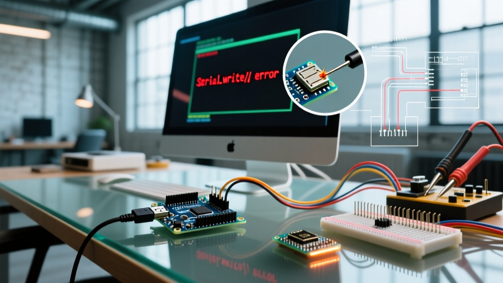

The Anatomy of a Serial Write Failure
Serial communication remains the bedrock of microcontroller debugging and data telemetry. However, when you attempt to write to serial port Arduino configurations, the process is rarely as simple as calling Serial.print(). A failure to transmit or receive data can stem from the physical USB cable, the onboard USB-to-UART bridge, the operating system's driver stack, or the microcontroller's internal hardware buffers.
As of 2026, the proliferation of USB-C connectors, advanced 32-bit ARM Cortex-M0+ boards, and ultra-low-cost clone boards has introduced new layers of complexity to serial diagnostics. This guide provides a deep-dive error diagnosis framework for identifying and resolving serial write failures across the entire data path.
The Serial Data Path: Where Writes Fail
Before diagnosing, you must understand the journey a byte takes when you write to the serial port. On a classic Arduino Uno R3, the path is:
- MCU USART: The ATmega328P shifts data out of its TX pin via the Universal Synchronous and Asynchronous serial Receiver and Transmitter (USART).
- USB-to-UART Bridge: An ATmega16U2 (on genuine boards) or a CH340G/CP2102 (on clones) converts the UART logic levels to USB D+/D- differential signaling.
- Physical Layer: The USB cable carries the signal to the host PC.
- OS Driver Stack: The host OS enumerates the device as a virtual COM port (VCP).
- Application Layer: The Arduino IDE, PuTTY, or your custom Python script reads/writes to the VCP.
A failure at any of these five nodes will result in a broken serial link. Let us break down the specific symptoms and their root causes.
Symptom 1: "Serial Port Busy" or Access Denied Errors
The Error: When compiling and uploading, or opening the Serial Monitor, the IDE throws: processing.app.debug.RunnerException: Serial port 'COM3' already in use. Try quitting any programs that may be using it.
The Diagnosis: The operating system enforces exclusive locks on serial ports. If a background process has opened the file descriptor for the COM port, the Arduino IDE cannot acquire the write lock.
Common Culprits and Fixes
- 3D Printing Slicers: Software like Cura or PrusaSlicer continuously polls serial ports to auto-detect connected 3D printers. Disable the USB polling feature in your slicer's preferences.
- Ghost Processes: A previous instance of the Arduino IDE or a crashed Python
pyserialscript may still hold the port. - OS-Level Resolution (Linux/macOS): Open your terminal and identify the process locking the port using
lsof. For example, if your board is on/dev/ttyUSB0, run:
sudo lsof | grep ttyUSB0
Once you have the Process ID (PID), kill it forcefully:
sudo kill -9 [PID] - OS-Level Resolution (Windows 11): Open Device Manager, locate the COM port under 'Ports (COM & LPT)', right-click, and select 'Disable Device', then immediately 'Enable Device' to force the OS to drop all file handles.
Symptom 2: Garbled Output and Framing Errors
The Error: You successfully write to the serial port, but the Serial Monitor displays a stream of question marks (?????), wingdings, or random ASCII characters.
The Diagnosis: This is a classic baud rate mismatch or clock drift issue. Serial communication relies on both devices agreeing on the exact timing of each bit. If the timing drifts by more than 2-3%, the receiver samples the bit in the wrong part of the voltage window, resulting in a framing error.
The Ceramic Resonator Problem on Clone Boards
Genuine Arduino boards use precision quartz crystals (typically 16.000 MHz) with a tolerance of ±10 to ±30 ppm. However, to cut costs, many $4 to $8 clone boards manufactured for the maker market use ceramic resonators. Ceramic resonators have a much wider tolerance, often ±0.5% (5000 ppm).
While a 0.5% error is perfectly acceptable at 9600 baud, it becomes catastrophic at higher speeds. According to SparkFun's Serial Communication Tutorial, higher baud rates require tighter timing margins.
| Target Baud Rate | Bit Duration | Max Tolerable Error | Ceramic Resonator Viable? |
|---|---|---|---|
| 9600 | 104.16 µs | ±4.5% | Yes (Highly Reliable) |
| 57600 | 17.36 µs | ±2.5% | Borderline (Occasional Drops) |
| 115200 | 8.68 µs | ±1.5% | No (Frequent Framing Errors) |
| 250000 | 4.00 µs | ±1.0% | No (Total Failure) |
The Fix: If you are using a clone Nano or Uno with a ceramic resonator and need high-speed telemetry, drop your baud rate to 38400 or 57600. Alternatively, use the internal oscillator calibration routines if working with bare ATtiny or ATmega chips without external crystals.
Symptom 3: Total Silence (No Output on Write)
The Error: The code compiles and uploads perfectly. The TX LED blinks rapidly during upload, but when you open the Serial Monitor, the screen remains completely black.
Diagnosis A: The USB-C Charge-Only Cable
With the transition to USB-C on newer boards like the Arduino Uno R4 Minima and Nano ESP32, cable selection is critical. The USB-C market is flooded with 'charge-only' cables designed for cheap consumer electronics. These cables contain the VBUS (Power) and GND pins but lack the D+ and D- data lines. If your board powers on but the OS does not play the 'device connected' chime, swap to a verified data-sync cable.
Diagnosis B: The ATmega32U4 Native USB Quirk
If you are using an Arduino Leonardo, Micro, or Pro Micro (which utilize the ATmega32U4 chip), the MCU handles USB communication natively via its USB CDC controller, rather than through a secondary bridge chip. When the board resets, the USB connection is physically dropped and re-enumerated by the host OS. This enumeration process takes approximately 1.2 to 1.5 seconds.
If your sketch writes to the serial port immediately in the setup() function, those bytes are sent into the void before the PC has established the virtual COM port. The Arduino Serial Reference explicitly warns about this behavior.
The Fix: Always include a blocking while-loop at the top of your setup function for native USB boards:
void setup() {
  Serial.begin(115200);
  while (!Serial) {
    ; // Wait for serial port to connect. Needed for native USB.
  }
  Serial.println("System Initialized.");
}
Symptom 4: Dropped Bytes on High-Speed Writes
The Error: Your PC is writing configuration packets to the Arduino via a Python script, but the Arduino only processes the first few commands and ignores the rest. Alternatively, the Arduino is printing high-frequency sensor data, but the PC receives truncated lines.
The Diagnosis: You have exceeded the hardware serial buffer limit. The ATmega328P features a very small 64-byte hardware receive buffer in its SRAM. When a byte arrives via the RX pin, a hardware interrupt fires, moving the byte from the USART Data Register (UDR0) into this 64-byte ring buffer. If your main loop is bogged down by blocking code—such as delay(), long analogRead() averaging, or driving addressable LED strips via bit-banging—the buffer fills up. Once byte 65 arrives, it is silently discarded.
Implementing a Software Ring Buffer
To prevent data loss when writing large payloads to the Arduino, you must decouple the serial read process from your main application logic. As detailed in advanced MCU architecture guides like PJRC's UART and Serial Debugging Guide, utilizing a larger software buffer in the background is essential for robust telemetry.
Instead of reading byte-by-byte in the loop(), use non-blocking packet parsing:
const int BUFFER_SIZE = 256;
char rx_buffer[BUFFER_SIZE];
int buffer_index = 0;

void loop() {
  while (Serial.available()) {
    char c = Serial.read();
    if (c == '\n') {
      rx_buffer[buffer_index] = '\0';
      processCommand(rx_buffer);
      buffer_index = 0;
    } else if (buffer_index < BUFFER_SIZE - 1) {
      rx_buffer[buffer_index++] = c;
    }
  }
  // Perform other non-blocking tasks here
}
Advanced Hardware Debugging: Logic Analyzers
When software diagnostics fail, you must inspect the physical layer. If you suspect the USB-to-UART bridge is failing to pass data to the main MCU, bypass the USB entirely.
- Connect a USB-to-TTL serial adapter (like an FTDI FT232RL breakout, typically $8-$12) directly to the Arduino's digital pins 0 (RX) and 1 (TX).
- Ensure you cross the lines: FTDI TX to Arduino RX, and FTDI RX to Arduino TX.
- Connect a shared Ground (GND).
- Use a logic analyzer, such as the Saleae Logic Pro 8 or a budget $10 24MHz 8-channel clone, to probe the TX and RX lines. Set the trigger to the falling edge of the start bit.
If the logic analyzer captures clean 3.3V or 5V square waves with correct start/stop bits, but the MCU does not react, your issue lies in the MCU's USART configuration registers (UCSR0A/B/C) or a fried RX pin. If the signal is degraded with slow rise times, you may have a parasitic capacitance issue on your breadboard or a failing USB-Serial bridge chip.
Diagnostic Matrix: Symptom to Solution
| Observed Symptom | Probable Root Cause | Immediate Action Required |
|---|---|---|
| Port Busy / Access Denied | Background process holding VCP lock | Kill slicer apps or use lsof / Device Manager reset |
| Garbage Characters | Baud mismatch or ceramic resonator drift | Verify Serial.begin() matches monitor; drop to 9600 baud |
| Total Silence (No Text) | Charge-only cable or missing while(!Serial) | Swap USB cable; add blocking loop for 32U4/ESP32-S2/S3 boards |
| Truncated Data / Drops | 64-byte hardware buffer overflow | Implement non-blocking ring buffer; remove delay() calls |
| Upload Fails / Timeout | CH340 driver signature enforcement | Install official WCH CH341SER driver; disable auto-reset capacitor |
Summary
Troubleshooting serial communication requires a systematic elimination of variables from the application layer down to the silicon. By understanding the limitations of hardware buffers, the quirks of native USB enumeration, and the physical realities of USB cabling and clock tolerances, you can rapidly diagnose why your system fails to write to the serial port. Always verify your physical connections first, respect the 64-byte hardware limits of legacy 8-bit AVRs, and leverage logic analyzers when the software stack obscures the underlying electrical reality.