
The Challenge of Interfacing an Arduino Thermocouple
Measuring extreme temperatures in DIY kilns, reflow ovens, or industrial heaters requires more than a standard thermistor. This is where an arduino thermocouple setup becomes essential. Thermocouples, particularly the ubiquitous K-type, can measure temperatures from -270°C up to 1250°C. However, they operate on the Seebeck effect, generating a minuscule voltage output—typically around 41 microvolts per degree Celsius. The Arduino's internal 10-bit ADC is entirely incapable of resolving these microvolt changes directly.
To bridge this gap, makers must use a dedicated thermocouple amplifier IC. These chips handle signal amplification, analog-to-digital conversion, and the critical task of Cold Junction Compensation (CJC). Without CJC, the temperature reading will drift based on the ambient temperature of your breadboard or PCB, rendering your high-temperature measurements useless.
Choosing the Right Amplifier IC for Your Project
Before wiring anything, you must select the appropriate interface chip. The market is dominated by three Maxim Integrated (now Analog Devices) chips, each catering to different precision requirements and budgets.
| IC Model | Resolution | Supported Types | Est. Price (2024) | Best Use Case |
|---|---|---|---|---|
| MAX6675 | 12-bit | K-Type Only | $4.00 | Basic hobby projects, 0-1024°C limit |
| MAX31855 | 14-bit | K, J, T, N, E, R, S, T | $8.50 | Standard maker projects, fault detection |
| MAX31856 | 19-bit | All Standard Types | $15.00 | High-precision lab equipment, 50/60Hz filtering |
For the vast majority of Arduino projects, the MAX31855 offers the best balance of cost and features. It provides built-in fault detection for open circuits and shorts, which the older MAX6675 lacks. If you are building a high-end PID controller where 50/60Hz AC noise from heating elements is a concern, the MAX31856 is worth the premium due to its programmable notch filters.
Hardware Wiring: SPI Pinout for Arduino Uno
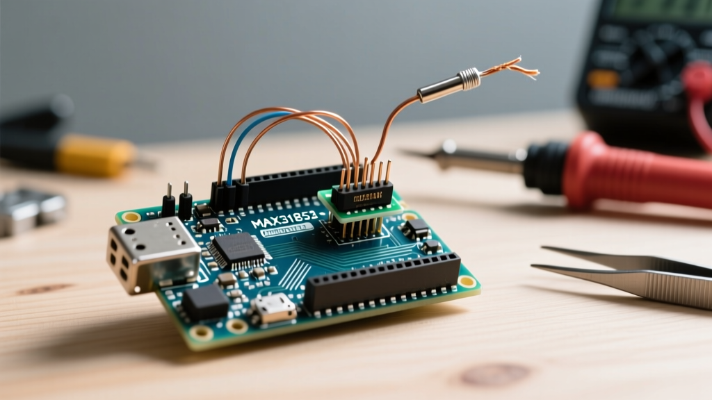
Thermocouple amplifiers communicate via the SPI (Serial Peripheral Interface) protocol. While software SPI is possible, utilizing the Arduino's hardware SPI pins ensures faster, more reliable data transfer, which is crucial when sampling temperatures rapidly for PID control loops.
Standard Hardware SPI Connections
- VCC: Connect to 3.3V or 5V (verify your specific breakout board's voltage regulator).
- GND: Connect to Arduino GND.
- SCK (Clock): Connect to Arduino Pin 13 (Hardware SPI).
- SO / MISO (Data Out): Connect to Arduino Pin 12 (Hardware SPI).
- CS (Chip Select): Connect to any digital pin (e.g., Pin 10).
Note: The SI/MOSI pin is not used on the MAX31855, as it is a read-only device. The MAX31856, however, requires MOSI (Pin 11) to configure its internal registers.
Writing the Arduino Sketch for K-Type Sensors
To interface with the hardware, we will use the Adafruit MAX31855 Library. This library abstracts the bitwise operations required to parse the 32-bit data packet returned by the IC.
#include <SPI.h>
#include <Adafruit_MAX31855.h>

// Define hardware SPI pins
#define MAXDO   12
#define MAXCS   10
#define MAXCLK  13

// Initialize the library with hardware SPI
Adafruit_MAX31855 thermocouple(MAXCS);

void setup() {
  Serial.begin(9600);
  Serial.println("Initializing Arduino Thermocouple...");

  // Wait for MAX chip to stabilize
  delay(500);

  if (!thermocouple.begin()) {
    Serial.println("ERROR: MAX31855 not found!");
    while (1);
  }
}

void loop() {
  // Read the internal CJC temperature
  float internalTemp = thermocouple.readInternal();
  Serial.print("Internal (CJC) Temp = ");
  Serial.println(internalTemp);

  // Read the thermocouple tip temperature
  double celsius = thermocouple.readCelsius();

  // Check for hardware faults
  uint8_t fault = thermocouple.readFault();
  if (fault) {
    handleFault(fault);
  } else {
    Serial.print("Thermocouple Temp = ");
    Serial.println(celsius);
  }

  delay(1000);
}

void handleFault(uint8_t fault) {
  if (fault & MAX31855_FAULT_OPEN) Serial.println("FAULT: Open Circuit");
  if (fault & MAX31855_FAULT_SHORT_GND) Serial.println("FAULT: Short to GND");
  if (fault & MAX31855_FAULT_SHORT_VCC) Serial.println("FAULT: Short to VCC");
}
Understanding the Data Packet
The MAX31855 outputs a 32-bit integer. Bits D[31:18] contain the 14-bit thermocouple temperature data, while bits D[15:4] contain the 12-bit internal cold-junction temperature. Bit D16 indicates a fault, and bits D[2:0] specify the fault type. The Adafruit library handles this bit-shifting automatically, but understanding the underlying architecture is vital when debugging I2C/SPI bus collisions.
Advanced Troubleshooting: Noise, EMI, and Ground Loops
The most common issue makers face when deploying an arduino thermocouple in a real-world heating environment is erratic data or sudden IC failure. Thermocouple wires act as highly efficient antennas, picking up electromagnetic interference (EMI) from nearby AC mains, solid-state relays (SSRs), and PWM signals.
Expert Insight: If your temperature readings jump wildly when your AC heater turns on, you are experiencing EMI injection. The microvolt-level signal of the thermocouple is easily overpowered by the switching noise of an SSR. Always use twisted-pair thermocouple wire and route it as far away from AC mains as physically possible.
Decoding Common Fault States
- FAULT_OPEN: The amplifier cannot detect a complete circuit. This usually means the thermocouple probe is disconnected, the wire has snapped inside the ceramic bead insulation, or the screw terminals on the breakout board are loose.
- FAULT_SHORT_GND / SHORT_VCC: The thermocouple wire has breached its insulation and is touching a grounded metal chassis or a live voltage source. This is common in DIY reflow ovens where the K-type probe touches the metal heating element.
The Ground Loop Problem with AC Heaters
When measuring the temperature of a metal block heated by an AC cartridge heater, a dangerous ground loop can occur. AC leakage current from the heater can travel through the metal block, into the thermocouple sheath, and down the ground wire of your Arduino, potentially destroying the MAX31855 IC.
To solve this, you have three options:
- Use an ungrounded thermocouple (the internal junction is isolated from the metal sheath with magnesium oxide powder).
- Implement a galvanic isolator (like the ISO124) between the thermocouple and the amplifier.
- Ensure the metal block and the Arduino share a single, robust common ground point to prevent potential differences.
Calibration and Final Deployment Tips
Out of the box, a standard K-type thermocouple has an accuracy of roughly ±2.2°C or ±0.75%. For applications like 3D printer hotends or basic kiln monitoring, this is sufficient. However, for scientific or culinary applications requiring higher precision, you must perform a multi-point calibration.
Boil distilled water (100°C at sea level) and use a slurry of crushed ice and distilled water (0°C) to establish baseline offsets. Apply these offsets in your Arduino sketch by adding a simple calibration constant to the readCelsius() return value. For comprehensive details on SPI bus management and timing, refer to the official Arduino SPI Reference Documentation. For deeper hardware specifications, the Analog Devices MAX31855 Datasheet remains the definitive guide to maximizing your sensor's potential.
By selecting the correct amplifier IC, adhering to strict SPI wiring practices, and proactively managing EMI, your arduino thermocouple setup will deliver reliable, high-temperature data for years of continuous operation.