
Why Your DIY Arduino SPL Meter is Giving Erratic Readings
Building a Sound Pressure Level (SPL) meter with an Arduino is a classic electronics project, but transitioning from a blinking LED to a calibrated acoustic measurement tool introduces a host of analog and mathematical hurdles. If your Arduino SPL meter is suffering from erratic baseline noise, flattened readings at high volumes, or dB(A) values that drift wildly from commercial reference meters, you are likely dealing with one of three core bottlenecks: hardware Automatic Gain Control (AGC), ADC reference noise, or flawed RMS sampling math.
In this comprehensive troubleshooting guide, we will diagnose the exact failure modes of popular microphone modules like the MAX9814 and MAX4466, fix your sampling windows to meet IEC 61672 standards, and calibrate your sketch for real-world accuracy in 2026.
The AGC Trap: MAX9814 vs. MAX4466 Hardware Limitations
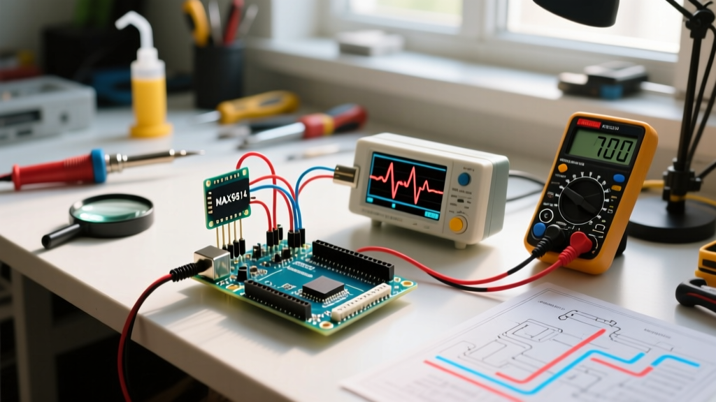
The most common reason an Arduino SPL meter fails to scale linearly at higher volumes (above 75 dB) is the use of the MAX9814 microphone amplifier module. While the MAX9814 (often sold as the Adafruit 1713 for ~$9.95) is an excellent module for voice recording, it features a built-in Automatic Gain Control (AGC) circuit.
How AGC Ruins SPL Linearity
The AGC dynamically adjusts the amplifier's gain based on the input volume. When the room is quiet, the gain is high (up to 60dB). When a loud noise occurs, the AGC compresses the gain down to 40dB or 50dB to prevent clipping. Because an SPL meter relies on a strict, linear mathematical relationship between voltage output and acoustic pressure, the AGC effectively destroys your calibration curve. Your meter will read accurately at 50 dB, but severely under-report at 90 dB.
The Fix: Switch to Fixed-Gain or Digital Modules
If you require linear acoustic measurement, you must bypass analog AGC. You have two primary upgrade paths:
- MAX4466 (Fixed Analog Gain): Priced around $7.95, this module uses a potentiometer to set a fixed hardware gain (typically 25x to 125x). It does not compress loud sounds, making it ideal for analog SPL metering up to ~100 dB before ADC clipping.
- INMP441 (I2S Digital MEMS): For professional-grade DIY builds, bypass the Arduino's noisy 10-bit ADC entirely. The INMP441 (~$4.00) outputs a 24-bit digital I2S stream directly to an ESP32 or Arduino Nano 33 BLE, eliminating analog cable noise and AGC compression.
Eliminating Baseline Noise and ADC Jitter
If your serial monitor shows the dB value jumping between 35 dB and 45 dB in a dead-silent room, your issue is power supply noise and ADC reference instability.
Step 1: Clean the AREF (Analog Reference)
By default, the Arduino Uno and Nano use the 5V USB rail as the analog reference. USB power from modern switching wall adapters is notoriously noisy, injecting 20-50mV of ripple into your ADC readings. Since a 10-bit ADC on a 5V scale resolves down to ~4.8mV per step, USB ripple translates directly to massive dB jitter.
The Fix: Switch your analog reference to the internal 1.1V bandgap reference or use an external precision voltage reference. If using the internal 1.1V reference, you must add a 0.1µF ceramic capacitor between the AREF pin and GND to stabilize the internal bandgap, and adjust your microphone module's DC bias to sit at 0.55V (half of 1.1V).
// Add this to your setup() function to use the internal 1.1V reference
analogReference(INTERNAL); // Use INTERNAL1V1 for Arduino Mega
Step 2: Implement a Hardware Low-Pass Filter
Electromagnetic interference (EMI) from nearby Wi-Fi routers or switching power supplies can couple into the high-impedance analog trace of your microphone. Solder a simple RC low-pass filter (e.g., a 100Ω resistor in series with the analog signal line, and a 0.1µF capacitor from the ADC input pin to GND). This creates a cutoff frequency of roughly 15.9 kHz, filtering out high-frequency RF noise without affecting audible acoustic frequencies.
The Math Problem: Peak-to-Peak vs. True RMS
A critical flaw in 90% of beginner Arduino SPL sketches is the use of Peak-to-Peak (P2P) voltage calculations instead of Root Mean Square (RMS). Sound pressure is a measure of acoustic power, which correlates to the RMS voltage of the microphone's AC signal, not its maximum peak excursion.
Why Peak-to-Peak Fails
P2P simply subtracts the minimum ADC reading from the maximum ADC reading over a sampling window. This method is highly susceptible to single-sample noise spikes and does not account for the waveform's actual energy distribution. A single EMI spike will artificially inflate your dB reading.
Implementing True RMS in C++
To achieve accurate readings, you must sample the AC-coupled signal, square the deviations from the DC bias, average those squares, and take the square root. According to Arduino's official analog documentation, maximizing the sampling rate is crucial for capturing audio frequencies.
float calculateRMS(int samples) {
  long sumOfSquares = 0;
  int dcBias = 512; // Assuming 5V reference and 10-bit ADC

  for (int i = 0; i < samples; i++) {
    int rawValue = analogRead(A0);
    int deviation = rawValue - dcBias;
    sumOfSquares += (long)deviation * deviation;
  }

  float meanSquare = (float)sumOfSquares / samples;
  return sqrt(meanSquare);
}
Pro-Tip: To meet the IEC 61672 standard for a 'Fast' SPL meter time weighting, your sampling window must capture at least 125ms of audio. At a standard Arduino sampling rate of ~9kHz, set your samples variable to 1100.
Microphone Module Comparison Matrix
Choosing the right front-end hardware dictates your troubleshooting path. Refer to this matrix to identify your module's inherent limitations.
| Module | Gain Type | Output | Max Linear dB | Best Use Case |
|---|---|---|---|---|
| MAX9814 | AGC (Dynamic) | Analog | ~75 dB | Voice activation, clapping sensors |
| MAX4466 | Fixed (Potentiometer) | Analog | ~105 dB | General purpose SPL metering |
| INMP441 | Internal DSP | I2S Digital | 115+ dB | Precision acoustics, FFT analysis |
| Adafruit 1713 | AGC (Dynamic) | Analog | ~75 dB | Same as MAX9814 (Adafruit branding) |
Calibrating to Real-World dB(A)
Raw RMS voltage means nothing without a calibration offset. Furthermore, human hearing does not perceive all frequencies equally; we are less sensitive to low bass and high treble. Commercial meters apply an A-weighting filter to approximate human hearing, resulting in dB(A) readings. The OSHA occupational noise exposure standards strictly mandate A-weighted measurements for workplace safety compliance.
Hardware Limitation Warning: True A-weighting requires complex digital FIR/IIR filtering or precision analog op-amp filter networks. A standard Arduino Uno lacks the processing headroom to apply real-time A-weighting to raw ADC samples while maintaining a 125ms 'Fast' response window. For most DIY applications, we apply a static hardware offset calibrated against a known A-weighted reference source.
The Calibration Procedure
- Acquire a Reference: Borrow or purchase a calibrated commercial SPL meter (e.g., the Galaxy Audio CM-130 or RISEPRO decibel meter).
- Generate Pink Noise: Play calibrated pink noise through a studio monitor at a fixed distance (e.g., 1 meter). Avoid pure sine waves, as room standing waves will cause massive discrepancies between your reference meter and the Arduino.
- Record Baseline: Set the commercial meter to A-weighting and 'Fast' response. Note the reading (e.g., 85.0 dB).
- Calculate Offset: Read the raw RMS voltage from your Arduino serial monitor. Convert this to a raw dB value using the formula:
Raw_dB = 20 * log10(V_rms / V_ref). The difference between the commercial meter's reading and your Raw_dB is yourCALIBRATION_OFFSET.
// Apply this constant in your main loop
#define CALIBRATION_OFFSET 14.5
#define V_REF 0.00488 // 5V / 1024 steps

void loop() {
  float rmsVoltage = calculateRMS(1100) * V_REF;
  float rawdB = 20.0 * log10(rmsVoltage / 0.001); // 1mV reference baseline
  float finaldB_A = rawdB + CALIBRATION_OFFSET;

  lcd.print(finaldB_A);
  delay(50);
}
Edge Case: I2C LCD Freezes and Memory Leaks
Many makers pair their Arduino SPL meter with a 16x2 I2C LCD. A frequent troubleshooting ticket involves the display freezing or showing garbled characters after 10-15 minutes of continuous operation.
- I2C Bus Capacitance: Long, unshielded jumper wires between the Arduino and the I2C backpack act as antennas, corrupting the SDA/SCL lines. Ensure your I2C wires are under 12 inches, or solder 4.7kΩ pull-up resistors directly to the 5V and SDA/SCL lines on the backpack.
- Address Conflicts: Cheap I2C backpacks often default to address
0x27, but some batches use0x3F. Run an I2C scanner sketch to verify the exact hex address before hardcoding it. - String Fragmentation: Avoid using the
Stringclass in yourloop()to format dB values for the display. Continuous allocation and deallocation of theStringobject fragments the ATmega328P's limited 2KB SRAM, eventually causing a heap collision and system freeze. Usedtostrf()orsnprintf()with static character arrays instead.
Summary of Diagnostic Steps
If your Arduino SPL meter is misbehaving, follow this triage sequence:
- Readings flatten at high volume? Replace the MAX9814 with a fixed-gain MAX4466 or I2S INMP441.
- High baseline jitter in silence? Add an AREF capacitor, switch to the internal 1.1V reference, and implement an RC low-pass filter.
- Values jump wildly on single claps? Rewrite your sampling math from Peak-to-Peak to True RMS over a 125ms window.
- dB values don't match commercial meters? Calibrate using pink noise and apply a static A-weighting offset in your sketch.
By addressing the physical limitations of analog AGC and respecting the mathematical requirements of RMS acoustic power, your DIY Arduino SPL meter can achieve reliability that rivals entry-level commercial tools.