
The Hidden Power Drain: Why Your Arduino Sleep Mode Fails
Designing a battery-powered IoT sensor or remote weather station is a rite of passage for makers, but nothing kills a project faster than a dead battery. You write the code, put your microcontroller into sleep mode, and expect months of battery life. Instead, your multimeter reads a frustrating 12mA to 18mA of parasitic draw, and the device dies in a week. Worse, sometimes the board simply refuses to wake up from sleep, leaving you debugging a seemingly frozen chip.
Troubleshooting Arduino sleep issues requires looking past the IDE and understanding the intersection of silicon-level registers, onboard support circuitry, and interrupt vectors. Whether you are working with a classic ATmega328P-based board or an ESP32, achieving true microamp-level standby requires a systematic approach to both software configuration and hardware elimination.
ATmega328P vs. ESP32: Sleep Mode Baseline Metrics
Before troubleshooting, you must know what your hardware is actually capable of. Makers often confuse the microcontroller's theoretical sleep current with the entire development board's quiescent draw. Below is a comparison of theoretical versus real-world current consumption for popular architectures.
| Architecture | Sleep Mode | Theoretical MCU Draw | Real-World Dev Board Draw | Primary Culprits for Excess Draw |
|---|---|---|---|---|
| ATmega328P (Uno/Nano) | Power-Down | ~0.1 µA | 15.0 - 30.0 mA | USB-Serial (CH340/16U2), Power LED, LDO |
| ATmega328P (Pro Mini) | Power-Down | ~0.1 µA | 1.5 - 4.0 mA | Onboard Power LED, AMS1117 LDO quiescent current |
| Barebones ATmega328P | Power-Down (BOD Off) | ~0.1 µA | 0.15 - 0.3 µA | None (Ideal baseline) |
| ESP32 (DevKitC V4) | Deep Sleep | ~10 µA (RTC Domain) | 2.0 - 8.0 mA | CP2102 USB bridge, AMS1117 LDO, RGB LED |
Troubleshooting Software: Wake-Up Failures and Interrupts
If your multimeter shows low power consumption but your project never wakes up, the issue lies in your interrupt configuration or sleep register setup. The microcontroller is sleeping perfectly; it just has no alarm clock.
Fix 1: The Watchdog Timer (WDT) Trap
The Watchdog Timer is the most common method for waking an ATmega328P from Power-Down mode without external hardware. However, a frequent bug occurs when the WDT triggers a system reset instead of a wake-up interrupt. This happens if the WDIE (Watchdog Interrupt Enable) bit is cleared while the WDE (Watchdog Reset Enable) bit remains set.
The Fix: Ensure you are using the avr/wdt.h library correctly. Before entering sleep, you must explicitly set the WDT to interrupt mode, not reset mode. Inside your Interrupt Service Routine (ISR) for the WDT, you must clear the interrupt flag, or the MCU will immediately fall back asleep or reset upon the next timeout cycle.
Fix 2: Pin Change Interrupt (PCINT) Debounce Ghosting
Waking via a physical button or reed switch using Pin Change Interrupts often leads to 'ghost' wake-ups. If a floating pin picks up electromagnetic interference (EMI) from a nearby switching power supply, the MCU wakes up randomly, destroying your battery life.
The Fix: Never leave wake-up pins floating. Use a 10kΩ pull-up or pull-down resistor physically on the breadboard. Furthermore, enable the internal pull-up resistor in software (pinMode(pin, INPUT_PULLUP)) before executing the sleep command. According to the official Microchip ATmega328P specifications, enabling internal pull-ups prevents the input buffer from oscillating in the linear region, which can otherwise cause an additional 1-2 mA of shoot-through current inside the silicon.
Hardware Power Leaks: Why You Are Still Drawing 12mA
If your software is flawless but your multimeter still reads milliamps instead of microamps, your development board is working against you. Standard Arduino boards are designed for desktop prototyping, not ultra-low-power deployment.
The Onboard LED and LDO Tax
A standard Arduino Nano clone uses a CH340G USB-to-serial chip and an AMS1117-3.3 or NCP1117-5.0 voltage regulator. The CH340G alone draws roughly 12mA just being connected to VCC. The onboard power LED draws another 3mA to 5mA. Finally, the linear regulator has a quiescent current of 5mA to 10mA.
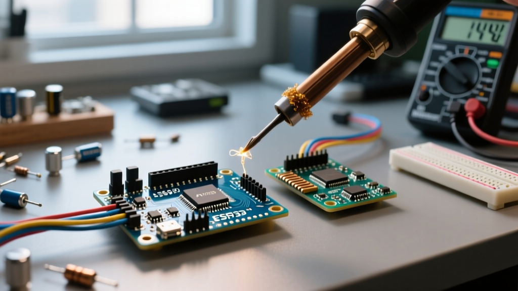
- LED Removal: Take a soldering iron set to 280°C, apply flux to the power LED pads, and use fine tweezers to flick the LED off the board. This instantly saves ~3mA.
- Regulator Bypass: If you are powering your project directly from a 3.3V battery (like a LiFePO4 cell), you can bypass the LDO entirely by cutting the VCC trace and feeding 3.3V directly into the 5V/VCC pin, bypassing the regulator's quiescent draw.
Disabling the ADC and Brown-Out Detector (BOD)
Even in Power-Down mode, certain internal peripherals can remain active if not explicitly shut down via software. The Analog-to-Digital Converter (ADC) and the Brown-Out Detector (BOD) are notorious power hogs.
To disable the ADC before sleeping, clear the ADEN bit in the ADCSRA register:
ADCSRA &= ~(1 << ADEN);
Disabling the BOD in software (for ATmega328P revision C and later) requires manipulating the MCUCR register right before the sleep instruction. As detailed in Nick Gammon's comprehensive power-saving guide, setting the BODS and BODSE bits disables the BOD, saving roughly 20µA to 40µA, which is massive when your target total draw is under 5µA.
Pro-Tip for ESP32 Makers: The ESP32 architecture is vastly different. You cannot use standard AVR sleep libraries. You must use theesp_sleep.hAPI. If you are using Deep Sleep, ensure you are isolating your GPIO pins. Floating GPIOs in deep sleep can cause internal leakage. Usertc_gpio_isolate()on unused pins to prevent phantom current drain. For deep architectural details, refer to the Espressif ESP-IDF Sleep Modes documentation.
Step-by-Step: Achieving True Microamp Sleep on a Pro Mini
The Arduino Pro Mini (3.3V, 8MHz) is the gold standard for low-power maker projects because it lacks the USB-to-serial chip. Here is the exact workflow to get it under 1µA.
- Desolder the Power LED: Locate the LED on the bottom edge and remove it with a hot iron.
- Remove the Voltage Regulator: If running directly from a 3.3V coin cell or LiPo, desolder the three-legged LDO on the side of the board to eliminate its 2mA quiescent draw.
- Upload the Sketch via FTDI: Use an external FTDI programmer (like the FT232RL) to upload your code. Crucially, disconnect the FTDI entirely before taking current measurements. Leaving the FTDI connected will skew your multimeter readings by 15mA+.
- Implement Software Shutdowns: Use the
LowPower.hlibrary or raw register manipulation to turn off the ADC, Timers 1 and 2, and the BOD before executing thesleep_cpu()assembly instruction. - Measure with a µCurrent Gold: Standard multimeters lack the burden voltage stability to measure sub-microamp currents accurately. Use a dedicated micro-current tool or an oscilloscope with a shunt resistor to verify your 0.15µA baseline.
FAQ: Common Arduino Sleep Edge Cases
Why does my Arduino wake up immediately after going to sleep?
This is almost always caused by an unhandled interrupt flag. If an external interrupt (INT0 or INT1) was triggered while the MCU was awake, the flag remains set in the EIFR register. The moment you call sleep_cpu(), the MCU sees the pending flag and wakes up instantly. Always clear the interrupt flags manually (e.g., EIFR = _BV(INTF0);) right before entering sleep.
Can I use I2C sensors while the Arduino is in sleep mode?
No. In true Power-Down mode, the system clock is halted, meaning the I2C (TWI) hardware module cannot generate SCL clock pulses. You must wake the MCU, take the I2C sensor reading, and then return to sleep. If you need continuous monitoring, consider using a sensor with a built-in hardware interrupt pin that can trigger the MCU's external wake pin when a threshold is crossed.
Does the ESP32 'Light Sleep' save more power than 'Deep Sleep'?
No. Deep Sleep turns off almost everything except the RTC controller and RTC memory, drawing roughly 10µA. Light Sleep keeps the digital peripherals and RAM powered, gating only the CPU clock and flash memory, resulting in a draw of roughly 0.8mA to 3mA. Use Light Sleep only if you need to maintain Wi-Fi connectivity or keep complex RAM states intact without the boot-up overhead of Deep Sleep.