
The Gap Between Simulation and Silicon
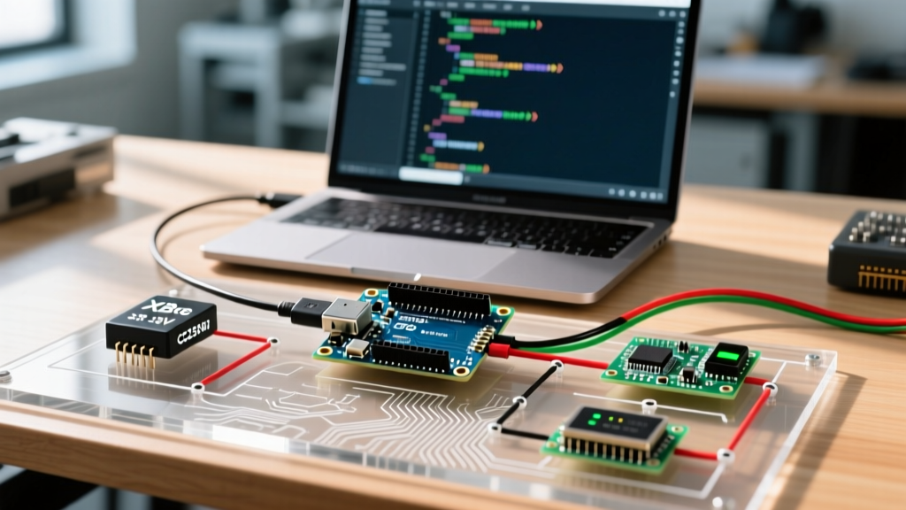
Using an arduino simulator like Wokwi, Tinkercad Circuits, or Proteus VSM is a cornerstone of modern embedded prototyping. Simulators allow makers and engineers to test logic, wire virtual breadboards, and debug code without risking physical components. However, as of 2026, the abstraction layers in these environments frequently mask critical hardware-level bugs. Code that compiles and runs flawlessly in a browser-based emulator often results in silent failures, frozen peripherals, or brownout resets when flashed to a physical ATmega328P or ESP32-S3.
This guide focuses strictly on error diagnosis: identifying why your simulated code fails on real hardware, understanding the hidden assumptions simulators make about memory and timing, and applying actionable fixes to bridge the gap between virtual and physical domains.
Expert Callout: The most dangerous simulator errors are not compilation failures. They are 'silent successes' where the emulator ignores physical constraints like I2C bus capacitance, SRAM heap fragmentation, or interrupt latency, leading you to believe your firmware is production-ready when it is not.The 'Infinite RAM' Trap: Diagnosing Heap Fragmentation
One of the most pervasive issues when transitioning from an arduino simulator to physical hardware is memory mismanagement. The standard Arduino Uno (ATmega328P) possesses a mere 2,048 bytes of SRAM. Many cloud simulators either fail to enforce strict memory boundaries or mask the effects of heap fragmentation caused by dynamic memory allocation.
The String Class Failure Mode
In Tinkercad and older versions of Proteus, utilizing the Arduino String class for heavy serial parsing or JSON manipulation might run indefinitely. The simulator's host environment (your PC's RAM) handles the background memory allocation seamlessly. On a real microcontroller, repeated concatenation and destruction of String objects fragments the 2KB SRAM heap. Eventually, a memory allocation fails, returning a null pointer or causing a silent crash that manifests as a frozen board with no serial output.
Diagnostic Fix: Static Allocation and FreeMemory()
To diagnose this before flashing, you must instrument your code to monitor SRAM. Inject a FreeMemory() diagnostic function into your loop() and print the available bytes to the serial monitor. If you see the free memory steadily declining over time in the simulator, you have a leak.
- Actionable Step: Replace all
Stringobjects with fixed-size character arrays (char buffer[64];) and use standard C functions likesnprintf()andstrcat(). - Actionable Step: Utilize the
F()macro for all serial print statements (e.g.,Serial.print(F("Status: OK"));) to keep string literals in Flash memory rather than loading them into SRAM at runtime.
According to the official Arduino Troubleshooting Guide, memory exhaustion is a primary cause of erratic board behavior, yet it remains largely invisible in default simulation views unless explicitly monitored.
I2C Bus Hangs and Pull-Up Resistor Emulation
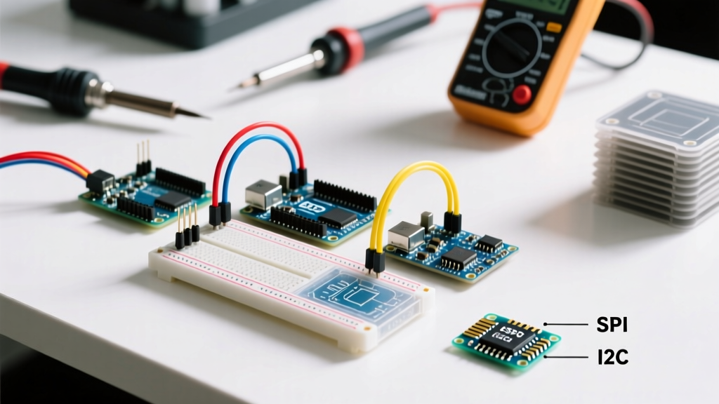
The I2C protocol requires pull-up resistors on both the SDA and SCL lines to function correctly. This is a frequent point of failure when moving from simulation to hardware.
The Tinkercad vs. Wokwi Discrepancy
When building circuits in Tinkercad Circuits, the simulator strictly enforces I2C physics. If you connect an MPU6050 or SSD1306 OLED display without placing 4.7kΩ pull-up resistors on the SDA/SCL lines, the Wire.endTransmission() function will block indefinitely, freezing your sketch. This is actually a highly accurate representation of real hardware.
Conversely, modern emulators like Wokwi sometimes emulate internal AVR pull-ups or assume ideal bus conditions. Your code might compile and run perfectly in Wokwi without external resistors, but when you wire the physical breadboard, the bus capacitance and lack of strong pull-ups cause signal degradation, resulting in NACK errors or complete bus lockups.
Diagnostic Checklist for I2C Failures
- Verify Return Codes: Never assume
Wire.endTransmission()succeeds. Capture its return value. A return of0means success;2indicates a NACK on address, often caused by missing pull-ups or incorrect I2C addresses. - Hardware Fix: Always include 4.7kΩ physical pull-up resistors to the 5V (or 3.3V) rail on your physical breadboard, regardless of whether the simulator required them.
- Bus Scanner: Run an I2C Scanner sketch on the physical hardware to verify device visibility before deploying your main application logic.
Clock Speed Mismatches and Timer Drifts
Timing errors are notoriously difficult to diagnose because the code logic is perfectly sound, but the hardware execution context is wrong. This frequently occurs in Proteus VSM when the virtual microcontroller's clock frequency does not match the compiled firmware's expectations.
The UART Garbage Output Symptom
If you compile a sketch in the Arduino IDE targeting a 16MHz ATmega328P, but your Proteus simulation component is configured with a default clock of 8MHz (or 1MHz for certain bare ATTiny chips), all hardware-timed peripherals will operate at half or 1/16th speed. The most immediate symptom is garbage output on the virtual serial terminal. The baud rate generator calculates timings based on 16MHz, but the CPU executes at 8MHz, resulting in malformed bits.
Interrupt Latency and Encoder Misses
Simulators often struggle with precise microsecond-level interrupt latency. If you are simulating a rotary encoder using attachInterrupt(), a simulator might process the state changes instantly. On physical hardware, contact bounce and interrupt latency can cause missed pulses. Always implement software debouncing or use hardware RC filters (e.g., 10kΩ resistor and 0.1µF capacitor) on physical interrupt pins, even if the arduino simulator shows clean square waves.
Simulator Error Handling & Diagnostic Features
Choosing the right environment depends on the specific errors you are trying to diagnose. Below is a comparison of how leading platforms handle common embedded edge cases in 2026.
| Simulator Platform | Core Engine | Memory Strictness | I2C Pull-Up Emulation | Best Diagnostic Use Case |
|---|---|---|---|---|
| Wokwi | Custom WebAssembly / ESP-IDF | Moderate (Warns on overflow) | Idealized (Masks missing resistors) | ESP32 Wi-Fi/BLE logic, RTOS task debugging |
| Tinkercad | AVR8js Backend | Strict (Halts on severe overflow) | Strict (Requires physical resistors) | Beginner wiring validation, basic AVR logic |
| Proteus VSM | Proprietary VSM CPU Models | Low (Abstracts heap limits) | Configurable via component props | Complex mixed-signal circuits, legacy AVR |
| SimulIDE | Open-source AVR/ARM | High (Cycle-accurate SRAM) | Strict | Low-level register debugging, timing analysis |
Cloud Compilation and Pin Mapping Errors
Modern web-based simulators rely on configuration files to map virtual pins to code. In Wokwi, this is handled via the diagram.json file. A common diagnostic headache occurs when the code compiles successfully, but peripherals fail to respond.
The ESP32 GPIO Matrix Trap
When simulating an ESP32-S3, developers often use LED_BUILTIN in their code. However, the built-in LED pin varies wildly between dev boards (e.g., GPIO 48 on the official DevKitC, but GPIO 2 on generic clones). If your diagram.json maps the virtual LED to GPIO 2, but your specific board definition in the cloud compiler targets GPIO 48, the simulation will run without errors, but the LED will never illuminate.
According to the official Wokwi documentation, ensuring exact parity between your diagram.json pin definitions and your physical dev board's pinout is critical. Always explicitly define pin numbers in your code (e.g., #define STATUS_LED 48) rather than relying on board-agnostic macros when transitioning from simulation to hardware.
Step-by-Step Diagnostic Workflow for Simulator-to-Hardware Failures
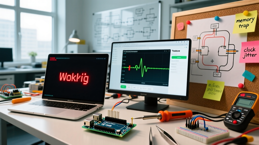
When your code works perfectly in the emulator but fails on your desk, follow this systematic diagnostic workflow to isolate the variable:
- Isolate the Power Domain: Simulators provide infinite, perfectly clean current. Real USB ports and breadboard power rails suffer from voltage drops. Measure your physical 5V and 3.3V rails with a multimeter under load. A drop below 4.7V will cause brownout resets on the ATmega328P.
- Verify Baud Rates and Clocks: Ensure your physical serial monitor matches the
Serial.begin()rate, and verify your IDE is compiling for the correct crystal oscillator speed (e.g., 16MHz vs 8MHz internal). - Inject Hardware-Agnostic Heartbeats: Add a simple
digitalWrite()toggle on a known-good pin with a 1-second delay at the very top of yourloop(). If the physical heartbeat LED blinks but the rest of the code fails, your issue is peripheral-specific (I2C/SPI), not a fundamental CPU crash. - Check Floating Pins: Simulators often default unconnected input pins to a stable LOW. Physical hardware will read electromagnetic noise, causing erratic behavior. Ensure all unused inputs are tied to GND or VCC via pull-down/pull-up resistors.
Conclusion
An arduino simulator is an invaluable tool for logic verification and rapid iteration, but it is not a perfect mirror of physical reality. By understanding the specific abstractions your chosen platform makes regarding memory allocation, I2C bus physics, and clock timing, you can preemptively diagnose errors before they manifest on the workbench. Always treat simulation as the first step in your debugging pipeline, not the final authority on firmware stability.