
The Reality of Interfacing Cameras with Microcontrollers
Integrating an Arduino camera module into a DIY electronics project is a rite of passage for many makers, but it is notoriously fraught with hardware and software pitfalls. Unlike simple sensors that output a single analog voltage or a slow I2C data stream, camera modules push massive amounts of pixel data at high frequencies. When you pair the limited SRAM and clock speeds of traditional 8-bit microcontrollers (like the ATmega328P on the Arduino Uno) with high-resolution sensors, the result is often a black screen, scrambled pixels, or silent initialization failures.
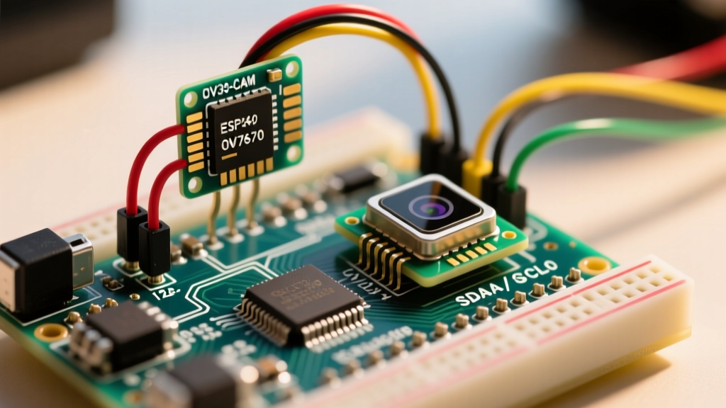
As of 2026, the market is dominated by three primary camera architectures for makers: the bare Omnivision OV7670, the Arducam Mini series (featuring the OV2640 with onboard FIFO buffering), and the integrated AI-Thinker ESP32-CAM. Each architecture fails in entirely different ways. This comprehensive troubleshooting guide bypasses generic advice and dives deep into the exact electrical failures, register misconfigurations, and power delivery issues that cause Arduino camera projects to fail—and exactly how to fix them.
Module Comparison: Know Your Hardware Limits
Before probing wires with a multimeter, you must understand the specific bottlenecks of your chosen module. Pricing and hardware architectures dictate the troubleshooting path.
| Module Type | Sensor / Core | Interface | Buffer / SRAM Requirement | Typical Cost (2026) | Primary Failure Mode |
|---|---|---|---|---|---|
| Bare OV7670 | Omnivision 0.3MP | Parallel 8-bit / SCCB (I2C) | Direct MCU SRAM (Requires 76KB+ for raw frame) | $4.00 - $6.00 | Out of Memory / Logic Frying |
| Arducam Mini 2MP Plus | OV2640 + AL422B FIFO | SPI (Data) / I2C (Config) | Onboard 384KB FIFO (MCU SRAM agnostic) | $18.00 - $22.00 | SPI Clock Degradation / I2C ACK |
| AI-Thinker ESP32-CAM | OV2640 + ESP32 SoC | Internal 8-bit / I2S | 520KB Internal + 4MB PSRAM | $7.00 - $10.00 | Power Brownouts / Wi-Fi TX Drops |
Fix 1: Resolving I2C Initialization and "ACK" Failures
The Symptom
You upload the Arducam or OV7670 initialization sketch. The Serial Monitor outputs Sensor not found, I2C ACK Error, or simply hangs after Initializing....
The Root Cause
Camera modules use the SCCB protocol (Omnivision's proprietary version of I2C) to configure internal registers. The most common cause of initialization failure on an Arduino Uno or Nano is a logic level mismatch. The OV7670 and OV2640 SCCB buses are strictly 3.3V tolerant. Feeding them 5V logic from an ATmega328P will either permanently degrade the sensor's internal pull-ups or cause the SCCB slave address (usually 0x30 or 0x3C) to be ignored due to voltage threshold clipping.
The Actionable Fix
- Implement Bidirectional Logic Level Shifting: Do not rely on resistor voltage dividers for I2C; they ruin the rise/fall times required for SCCB. Use a dedicated BSS138 MOSFET-based logic level shifter (costing about $1.50) between the Arduino's 5V SDA/SCL pins and the camera's 3.3V pins.
- Verify Pull-Up Resistor Values: SCCB requires pull-up resistors on the 3.3V side of the level shifter. If your wiring exceeds 10cm, parasitic capacitance increases. Drop the standard 10kΩ pull-ups to 4.7kΩ (for 100kHz bus speeds) or 2.2kΩ (for 400kHz) to ensure sharp signal edges.
- Check the VSYNC / HREF Polarity: If the I2C bus initializes but the capture hangs, verify your module's VSYNC polarity. Some bare OV7670 modules require a hardware inversion of the VSYNC pin, which can be toggled via register
0x15in the initialization array.
Fix 2: Eliminating the Dreaded Pink or Green Screen Tint
The Symptom
The camera successfully captures and streams an image to your PC or TFT display, but the entire image is washed out in a severe magenta, pink, or neon green tint.
The Root Cause
This is rarely a hardware defect. It is almost always a color matrix register misconfiguration or a byte-order parsing error in your Arduino sketch. The OV7670 outputs data in RGB565, YUV422, or Bayer format. If the sensor's internal Digital Signal Processor (DSP) is commanded to output RGB565, but the color matrix registers are left in their default YUV state, the MCU will interpret luminance and chrominance data as raw Red/Green/Blue pixels, resulting in the psychedelic tint.
The Actionable Fix
You must explicitly write the correct hex values to the sensor's color matrix registers during the setup() function. According to the ArduCAM Official GitHub Repository and Omnivision application notes, ensure the following registers are forced if using RGB565 on an OV7670:
REG_COM13(0x3D): Set to0x10(Enable RGB output, Gamma enable).REG_RGB444(0x8C): Set to0x00(Disable RGB444, enforce RGB565).REG_COM15(0x40): Set to0xD0(RGB565 output, full range).
If you are using an ESP32-CAM with the Arduino IDE, ensure your camera_config_t struct explicitly defines .pixel_format = PIXFORMAT_RGB565 and .frame_size = FRAMESIZE_QVGA. Higher resolutions without PSRAM enabled will force the driver to drop color depth to prevent heap allocation failures.
Fix 3: ESP32-CAM Brownout Detector and Power Starvation
Expert Insight: The ESP32-CAM is notorious for triggering the
Brownout detector was triggeredserial error. This is almost never a software bug; it is a severe power delivery failure compounded by RF transmission spikes.
The Root Cause
When the ESP32-CAM captures an image and simultaneously fires up the 2.4GHz Wi-Fi radio to transmit the payload, the module experiences transient current spikes up to 800mA. Standard FTDI USB-to-Serial adapters and cheap breadboard power supplies typically max out at 500mA. When the voltage on the 5V rail dips below 4.1V for even a few microseconds, the ESP32's internal brownout detector (BOD) resets the chip to protect the flash memory from corruption.
The Actionable Fix
- Bypass the Onboard AMS1117 Regulator: The onboard 3.3V LDO is highly inefficient and generates excessive heat. Power the ESP32-CAM's 3V3 pin directly using an external, high-quality buck converter (like the Pololu D36V50F3) capable of delivering 2A continuous current.
- Add Local Decoupling Capacitance: Solder a 1000µF electrolytic capacitor and a 100nF ceramic capacitor in parallel directly across the 5V and GND pins (or 3V3 and GND if bypassing the LDO) on the ESP32-CAM header. This provides the instantaneous microsecond current required during Wi-Fi TX spikes without relying on the long, inductive wires from your power supply.
- Disable the BOD (Software Workaround):strong> If you are constrained by hardware, you can lower the brownout threshold in the Arduino IDE. In your code, include
#include "soc/rtc_cntl_reg.h"and addWRITE_PERI_REG(RTC_CNTL_BROWN_OUT_REG, 0);at the very top of yoursetup()function. This disables the hardware reset, though it may lead to image corruption if the voltage drops too low. For more on ESP32 power management, refer to the Random Nerd Tutorials ESP32-CAM Troubleshooting Guide.
Fix 4: FIFO Buffer Overflows and SPI Clock Degradation
The Symptom
Using an Arducam Mini (OV2640/OV5642) with an Arduino Mega or Uno. The Serial monitor reports Capture Done, but the resulting image is half-blank, shifted, or entirely corrupted with horizontal tearing.
The Root Cause
The Arducam modules utilize an AL422B FIFO memory chip to bridge the gap between the camera's fast parallel output and the Arduino's slow SPI bus. Horizontal tearing occurs when the Arduino's SPI clock speed is set too high for the physical length of the jumper wires, causing bit-errors during the FIFO read phase. Alternatively, if the VSYNC interrupt is missed by the Arduino, the FIFO write pointer overflows, wrapping new pixel data over the beginning of the frame buffer.
The Actionable Fix
- Throttle the SPI Bus: In your sketch's initialization, locate the SPI clock divider. If you are using Dupont jumper wires longer than 15cm, parasitic capacitance will ruin signal integrity at 16MHz. Force the SPI clock to
SPI_CLOCK_DIV4(4MHz on a 16MHz Uno) orSPI_CLOCK_DIV8. You can verify the optimal speed using the SparkFun ESP32-CAM Hookup Guide methodologies for SPI bus testing. - Clear the FIFO Before Capture: Always explicitly flush the FIFO write pointer before triggering a new capture. Call
myCAM.flush_fifo()followed bymyCAM.clear_fifo_flag()immediately before asserting the capture start register. - Use Hardware Interrupts for VSYNC: Do not poll the VSYNC pin in the
loop(). Attach a hardware interrupt usingattachInterrupt(digitalPinToInterrupt(VSYNC_PIN), vsync_isr, RISING)to ensure the exact moment the frame finishes is caught, preventing FIFO overflow.
Advanced Diagnostic Checklist
If you have applied the fixes above and your Arduino camera is still failing, run through this rapid diagnostic checklist:
- Oscilloscope Probe on MCLK: The OV7670 requires a Master Clock (XCLK) between 10MHz and 48MHz. If you are generating this via an Arduino PWM pin, ensure the timer registers are configured for at least 16MHz. A missing MCLK will result in a completely dead sensor (no I2C ACK, no data).
- Check the PWDN and RESET Pins: On the ESP32-CAM, GPIO 32 controls the Power Down (PWDN) pin. It must be driven LOW to keep the sensor active. If your sketch leaves it floating or HIGH, the sensor remains in sleep mode.
- Inspect the Flex PCB Connector: The 24-pin FFC (Flat Flexible Cable) connector on Arducam and bare modules is incredibly fragile. Ensure the cable is seated perfectly straight and the retention flap is fully depressed. A 1mm misalignment will short the 3.3V rail to the data lines.
Final Thoughts
Troubleshooting an Arduino camera module requires shifting your mindset from standard low-speed sensor debugging to high-frequency signal integrity and strict power management. By respecting the 3.3V logic limits of SCCB buses, providing adequate bulk capacitance for RF transmission spikes, and carefully managing FIFO pointers via hardware interrupts, you can transform a frustrating, unstable camera project into a robust, reliable vision system.