
The Architecture of Arduino Serial Communication
Establishing a reliable Arduino serial connection is the foundational skill for any microcontroller project, whether you are streaming telemetry from a drone, debugging a robotic arm, or interfacing with industrial sensors. At its core, serial communication relies on Universal Asynchronous Receiver-Transmitter (UART) protocols to send data one bit at a time. However, as the maker ecosystem has evolved through 2026, the landscape has shifted from the classic 8-bit AVR chips to 32-bit ARM and RISC-V architectures, fundamentally changing how we configure and manage serial ports.
Unlike synchronous protocols like SPI or I2C, UART does not use a dedicated clock line. Instead, both the transmitter and receiver must agree on a specific timing configuration—known as the baud rate—to sample the voltage levels on the TX and RX lines accurately. A misconfiguration here doesn't just slow down your data; it results in complete communication failure or corrupted byte streams.
Hardware UART vs. Software Serial: Choosing the Right Engine
Modern microcontrollers offer multiple hardware UART peripherals, but legacy boards or pin-constrained designs often force developers to use software-based serial emulation. Understanding the architectural differences is critical for system stability.
| Feature | Hardware UART (Serial1, Serial2) | SoftwareSerial | AltSoftSerial / NeoSWSerial |
|---|---|---|---|
| CPU Overhead | Negligible (handled by hardware FIFO) | Extremely High (blocks CPU via interrupts) | Moderate (uses timer interrupts) |
| Max Reliable Baud | 2,000,000+ (chip dependent) | 115,200 (often fails above 57,600) | 31,250 (fixed pin constraints) |
| Simultaneous Ports | Yes (all ports active concurrently) | No (only one can listen at a time) | Yes, but conflicts with PWM/Timer1 |
| Best Use Case | GPS, LiDAR, high-speed telemetry | Low-speed config menus, basic debugging | Secondary low-speed sensor buses |
Expert Insight: If you are using an Arduino Uno R4 Minima (Renesas RA4M1) or a Nano ESP32, abandon SoftwareSerial entirely. These boards possess multiple native hardware UARTs and native USB-CDC capabilities. Relying on software emulation on 32-bit boards is an outdated practice that introduces unnecessary interrupt latency.
Configuring Baud Rates: The Mathematics of Reliability
The most common mistake in serial configuration is blindly defaulting to 9600 or 115200 baud without considering the microcontroller's clock source. The actual baud rate generated by the Arduino is derived from the system clock frequency divided by a hardware register value (UBRR on AVR chips). Because this division rarely results in a perfect integer, an inherent baud rate error is introduced.
The 16MHz Crystal Reality Check
For classic 16MHz Arduino boards (like the Uno R3 or Mega 2560), the math dictates some surprising realities about standard baud rates:
- 9600 Baud: ~0.2% error. Highly reliable, but painfully slow for large data payloads.
- 115200 Baud: ~2.1% error (without U2X double-speed mode). Generally tolerated by modern USB-to-Serial chips like the FT232RL or CH340, but can cause dropped packets over long RS-485 runs.
- 250000 Baud: 0.0% error. This is the hidden gem of 16MHz AVRs. If you need high-speed data streaming (e.g., raw ADC sampling or fast LiDAR mapping) and are communicating with another Arduino or a configurable PC serial terminal, 250000 baud is mathematically perfect and vastly outperforms 115200.
- 76800 Baud: 0.0% error. An excellent alternative if your receiving software doesn't support 250k.
Pro-Tip for PlatformIO Users: When configuring high-speed serial connections in PlatformIO, always verify your
board_build.f_cpusetting. If your custom board uses an internal RC oscillator instead of an external crystal, the clock tolerance can drift by up to 5%, making high-baud serial connections completely unstable. Always use external crystals for production serial links.
Wiring Topologies: TTL, RS-232, and RS-485
An Arduino's native UART pins output TTL-level signals (0V for logic low, 3.3V or 5V for logic high). Connecting these directly to industrial equipment or legacy PC ports will result in damaged silicon. You must match the physical layer protocol to your environment.
1. Point-to-Point TTL (Board-to-Board)
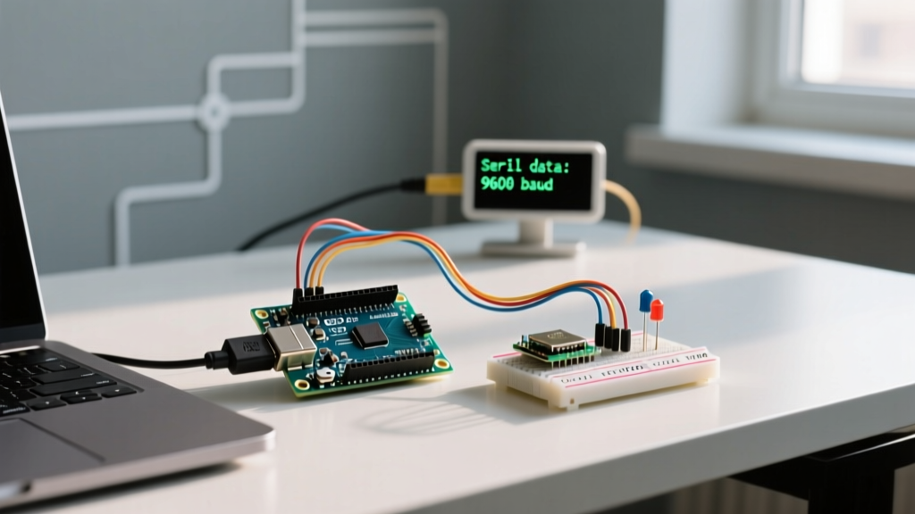
When connecting two Arduinos directly, wire the TX of Board A to the RX of Board B, and vice versa. Critical Requirement: You must connect a common Ground (GND) wire between the two boards. Without a shared ground reference, the voltage thresholds will float, resulting in gibberish data. If one board is 5V and the other is 3.3V (e.g., Uno to ESP32), use a bidirectional logic level converter (like the BSS138-based modules costing ~$1.50) to prevent overvoltage damage to the 3.3V RX pin.
2. Industrial RS-485 (Long Distance & Noisy Environments)
For runs exceeding 15 meters or environments with heavy electromagnetic interference (EMI), TTL is useless. RS-485 uses differential signaling over twisted pair cables, allowing distances up to 1,200 meters. To configure this, you need a MAX485 transceiver module (e.g., the HW-519 breakout).
RS-485 Half-Duplex Wiring Guide:
- VCC: Connect to Arduino 5V.
- GND: Connect to Arduino GND.
- RO (Receiver Out): Connect to Arduino RX pin.
- DI (Driver In): Connect to Arduino TX pin.
- DE & RE (Driver/Receiver Enable): Jumper these together and connect to a digital control pin (e.g., Pin 8). Set HIGH to transmit, LOW to receive.
- A & B: Connect to the twisted pair data lines. Always add a 120-ohm termination resistor across A and B at both ends of the bus to prevent signal reflection.
For deeper insights into physical layer standards, refer to the comprehensive SparkFun Serial Communication Tutorial, which covers the electrical differences between these standards in detail.
Advanced Configuration: Serial Buffer Management
By default, the Arduino AVR core allocates a mere 64 bytes for the serial receive buffer. If your Arduino is busy executing a blocking function (like driving a NeoPixel strip or writing to an SD card) and more than 64 bytes arrive on the serial port, the hardware FIFO overflows, and incoming data is permanently lost.
Expanding the Buffer in Arduino IDE
To prevent data loss in high-throughput applications, you must increase the buffer size. In the classic Arduino IDE, this requires modifying the core files:
- Navigate to your Arduino installation directory:
hardware/arduino/avr/cores/arduino/ - Open
HardwareSerial.hin a text editor. - Locate the line defining
SERIAL_RX_BUFFER_SIZE(usually around line 48). - Change the value from
64to256or512. - Save and recompile your sketch.
The PlatformIO Method (Recommended)
Modifying core files is bad practice for version control. If you use PlatformIO, you can override the buffer size dynamically using build flags in your platformio.ini file without touching the core source code:
build_flags = -DSERIAL_RX_BUFFER_SIZE=256
This ensures your buffer configuration travels with your repository and survives IDE updates. For more on core serial functions and buffer behaviors, consult the official Arduino Serial Reference Documentation.
Troubleshooting Common Serial Connection Failures
Even with perfect code, physical layer issues frequently sabotage serial connections. Use this diagnostic matrix to isolate failures.
| Symptom | Probable Cause | Actionable Solution |
|---|---|---|
| Complete Gibberish (e.g., '????') | Baud rate mismatch or clock drift. | Verify both ends match exactly. If using an internal oscillator, switch to 9600 baud or add an external crystal. |
| Intermittent Dropped Characters | Buffer overflow or EMI on TX/RX lines. | Increase SERIAL_RX_BUFFER_SIZE. Route serial wires away from AC mains or PWM motor lines. |
| Works on USB, Fails on Hardware Pins | TX/RX swapped or USB-CDC vs Hardware UART confusion. | Remember: Serial is USB on Leonardo/ESP32. Serial1 is hardware pins 0/1. Ensure TX connects to RX. |
| RS-485 Bus Locks Up | Missing termination or DE/RE pin stuck HIGH. | Verify 120-ohm resistors on ends. Ensure code sets DE/RE pin LOW immediately after Serial.flush(). |
Frequently Asked Questions
Can I use multiple serial ports on an Arduino Uno R3?
The Uno R3 only has one hardware UART (pins 0 and 1), which is shared with the USB-to-Serial ATmega16U2 chip. If you need a second port, you must use SoftwareSerial or upgrade to a Mega 2560 or Uno R4, which feature multiple dedicated hardware UARTs.
Why does my ESP32 serial connection drop at 1,000,000 baud?
While the ESP32 hardware supports 1M baud, the USB-to-UART bridge chip on many cheap dev boards (like the CP2102 or CH340) cannot reliably handle the USB polling overhead at that speed. Use 921600 baud instead, which is natively supported by most modern USB bridge chips and offers virtually identical throughput.
Do I need to call Serial.flush() before reading?
No. A common misconception is that Serial.flush() clears the incoming buffer. In modern Arduino cores (1.0 and above), Serial.flush() actually blocks the program until all outgoing data in the transmit buffer has finished sending. To clear the incoming buffer, use a while loop: while(Serial.available()) Serial.read();.
Mastering the Arduino serial connection requires moving beyond basic Serial.println() debugging. By understanding the mathematical realities of baud rate generation, respecting physical layer voltage requirements, and actively managing memory buffers, you can build robust, high-speed communication networks that survive the transition from the workbench to the real world.