
The Architecture of the InvenSense MPU-6050
When building motion-tracking projects, balancing robots, or stabilization gimbals, the intersection of the MPU6050 and Arduino remains one of the most reliable and cost-effective combinations available to makers. Originally developed by InvenSense (now a subsidiary of TDK), the MPU-6050 is a 6-axis Micro-Electro-Mechanical Systems (MEMS) sensor that combines a 3-axis gyroscope and a 3-axis accelerometer into a single silicon die. Unlike older multi-chip modules, this integrated approach minimizes cross-axis alignment errors, providing highly coherent spatial data.
However, simply connecting the sensor to a microcontroller is rarely enough to achieve professional-grade results. The true power of this chip lies in its onboard Digital Motion Processor (DMP), a dedicated hardware engine capable of executing complex sensor fusion algorithms—such as the Madgwick or Mahony filters—without burdening the Arduino's main CPU. In this comprehensive 2026 guide, we will bypass the superficial tutorials and dive deep into the electrical physics, I2C bus requirements, and calibration routines necessary to eliminate the infamous Z-axis gyro drift.
2026 Hardware BOM and Pricing
Before wiring, you must select the right components. While the bare MPU-6050 chip is a 4x4mm QFN package that is nearly impossible to hand-solder, the market is flooded with breakout boards. Below is the recommended Bill of Materials (BOM) for a robust prototype.
| Component | Specific Model / Variant | Est. Price (2026) | Engineering Notes |
|---|---|---|---|
| IMU Breakout | GY-521 (Generic) or Adafruit 3885 | $2.50 - $9.95 | Generic GY-521 boards often lack proper decoupling capacitors. Adafruit boards include onboard voltage regulation. |
| Microcontroller | Arduino Uno R4 Minima | $22.00 | The R4's Renesas RA4M1 ARM Cortex-M4 processes DMP FIFO data much faster than the legacy ATmega328P. |
| Logic Level Shifter | 4-Channel Bi-Directional (BSS138) | $1.50 | Absolute requirement if using 5V Arduinos with generic 3.3V GY-521 clones. |
| Pull-Up Resistors | 4.7kΩ Through-Hole (1/4W) | $0.10 | Used for external I2C bus stabilization on long wire runs. |
Precision Wiring and I2C Bus Physics
The most common point of failure when integrating the MPU6050 and Arduino is a misunderstanding of I2C bus voltage levels and pull-up resistor topology. The MPU-6050 operates strictly at 3.3V logic. If you are using an official Arduino Uno R3 or R4, the microcontroller's I2C pins (SDA/SCL) operate at 5V. Feeding 5V directly into the SDA/SCL pins of the MPU-6050 violates the absolute maximum ratings outlined in the TDK InvenSense Register Map, leading to silicon degradation and eventual thermal failure of the sensor.
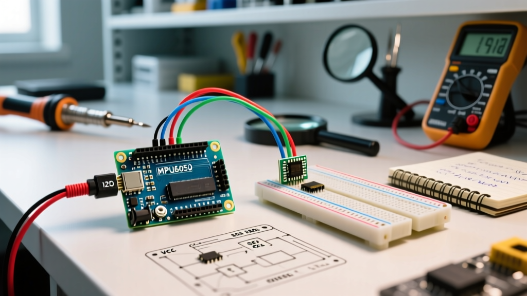
Furthermore, cheap GY-521 breakout boards route their onboard 4.7kΩ pull-up resistors directly to the VCC pin. If you power the GY-521 VCC pin with 5V from the Arduino, the I2C lines are pulled up to 5V, damaging the chip. The correct wiring protocol is to power the GY-521 VCC pin with 3.3V, and use a bi-directional logic level shifter for the SDA and SCL lines.
Pinout Matrix and AD0 Configuration
| MPU-6050 Pin | Arduino Uno R4 Pin | Function & Critical Rules |
|---|---|---|
| VCC | 3.3V | Do NOT use 5V on generic clones. Use 5V only on boards with an onboard LDO (like Adafruit). |
| GND | GND | Must share a common ground plane with the Arduino. |
| SCL | A5 (via Level Shifter) | I2C Clock. Keep wire length under 30cm to avoid capacitance issues. |
| SDA | A4 (via Level Shifter) | I2C Data. Ensure 4.7kΩ pull-ups are present on the 3.3V side. |
| XDA / XCL | Not Connected | Reserved for auxiliary I2C master mode (e.g., connecting an external magnetometer). |
| AD0 | GND | I2C Address Select. Tie to GND for 0x68. Tie to 3.3V for 0x69. Never leave floating. |
| INT | D2 | Interrupt pin. Crucial for reading the DMP FIFO buffer without polling. |
Software Strategy: Raw Registers vs. the DMP
When querying the sensor, developers generally choose between reading raw accelerometer/gyroscope registers or utilizing the onboard DMP. Reading raw data via the standard Arduino Wire Library Reference is straightforward but computationally expensive. You must manually implement a Complementary Filter or Kalman Filter in your Arduino sketch to fuse the noisy accelerometer data with the drifting gyroscope data.
Conversely, the DMP handles this sensor fusion internally at up to 200Hz, outputting clean, drift-compensated Quaternions. To access the DMP, we strongly recommend bypassing basic libraries and using Jeff Rowberg's I2Cdevlib Repository. This library contains the proprietary DMP firmware binary and handles the complex FIFO buffer management required to prevent data overflow.
Implementing the Interrupt-Driven FIFO Read
A critical mistake beginners make is using delay() or constant polling to read the MPU-6050. The DMP writes quaternion data into a 1024-byte internal FIFO buffer. If the Arduino does not read this buffer fast enough, it overflows, resulting in a 'FIFO Overflow' error and locked-up I2C communication. By wiring the INT pin to Arduino Digital Pin 2, you can attach an interrupt service routine (ISR) that sets a boolean flag the millisecond the DMP has fresh data ready, ensuring zero dropped packets.
Step-by-Step Calibration for Z-Axis Drift
Even with the DMP active, MEMS gyroscopes suffer from inherent manufacturing biases, manifesting as Z-axis yaw drift over time. To achieve sub-degree accuracy, you must calculate and write factory offsets to the sensor's internal registers.
- Physical Leveling: Place the Arduino and MPU-6050 on a machined, perfectly flat surface. Use a digital spirit level to ensure the X and Y axes are within 0.1 degrees of true horizontal.
- Thermal Stabilization: Power the circuit and allow it to run for 10 minutes. The internal temperature sensor must stabilize, as MEMS bias is highly temperature-dependent.
- Iterative Offset Calculation: Using the
IMU_Zerocalibration sketch (available in the I2Cdevlib examples), the Arduino will read 10,000 samples, calculate the mean deviation from zero, and write the inverse values to the MPU-6050's offset registers (0x13 to 0x18 for accelerometers, 0x1A to 0x1F for gyros). - EEPROM Storage: The MPU-6050 is volatile; it forgets offsets on power loss. Your Arduino sketch must store these calculated offsets in its internal EEPROM and write them back to the IMU during the
setup()function on every boot.
Advanced Troubleshooting and Edge Cases
When deploying the MPU6050 and Arduino in real-world environments, you will inevitably encounter edge cases that standard tutorials ignore.
- The 36.34°C Temperature Quirk: When the DMP is active, the internal temperature sensor often locks at a static reading of roughly 36.34°C. This is a known silicon bug related to the DMP overriding the temperature ADC clock. If your project requires ambient temperature tracking, you must use an external sensor like the BME280.
- Vibration-Induced Clipping: If mounting the sensor on a drone or motorized chassis, high-frequency vibrations will saturate the accelerometer's ADC, causing 'clipping' (maxing out at ±16g). You must mechanically isolate the GY-521 board using sorbothane foam tape or O-rings, and configure the DLPF (Digital Low Pass Filter) register to 42Hz or 98Hz to reject motor harmonics.
- I2C Bus Lockups: If the Arduino resets while the MPU-6050 is transmitting data, the SDA line can be held low by the sensor, locking the I2C bus. Implement a software I2C bus recovery routine in your code that toggles the SCL pin manually 9 times to force the sensor to release the bus.
Expert Insight: Never rely on the internal voltage regulator of a generic GY-521 board to power external peripherals. The onboard LDO is typically a low-grade SOT-23 package capable of sourcing less than 50mA. Drawing excess current will cause voltage sag, instantly corrupting the I2C logic levels and triggering a watchdog reset on your Arduino.
Frequently Asked Questions (FAQ)
Can I connect multiple MPU-6050 sensors to a single Arduino?
Yes, but with limitations. The MPU-6050 only supports two I2C addresses (0x68 and 0x69) via the AD0 pin. To use more than two, you must utilize an I2C Multiplexer like the TCA9548A, which allows you to route up to 8 separate I2C buses through a single Arduino SDA/SCL pair.
Why is my MPU-6050 heating up to the touch?
The MPU-6050 typically runs about 5°C to 10°C above ambient temperature due to the internal MEMS drive circuitry and the DMP processor. However, if the chip is too hot to touch, you have likely wired VCC to 5V on a 3.3V clone board, causing the internal LDO to dissipate excess power as heat. Disconnect immediately to prevent permanent silicon damage.
How does the MPU-6050 compare to modern alternatives like the BNO085?
While the MPU-6050 remains the undisputed king of budget IMUs, the BNO085/BNO086 offers superior sensor fusion via its built-in ARM Cortex-M0+ and supports absolute orientation using an integrated magnetometer. However, the BNO085 costs roughly 5x more and requires complex SPI/I2C packet parsing, making the MPU6050 and Arduino combination still the most practical choice for relative motion tracking and educational projects in 2026.