
The Anatomy of Arduino Remote Control Car Failures
Building an Arduino remote control car is a staple project for robotics enthusiasts, but transitioning from a breadboard prototype to a functional, driving chassis introduces complex electromechanical failures. When your rover stutters, drifts, or loses connection, the culprit is rarely the microcontroller's logic. Instead, failures stem from voltage starvation, inductive kickback, and RF impedance mismatches. This guide dissects the three most critical failure domains in custom RC builds: motor driver thermal throttling, transceiver brownouts, and analog-to-digital converter (ADC) noise, providing exact hardware and software fixes to get your vehicle back on the track.
Power Delivery and Motor Driver Bottlenecks
Most beginners default to the L298N dual H-bridge for their first builds. While ubiquitous and cheap, the L298N relies on older Bipolar Junction Transistor (BJT) technology. According to the Texas Instruments L298N datasheet, the BJT architecture introduces a combined voltage drop of approximately 2.0V to 2.5V across the internal transistors at a mere 1A load. If you power your Arduino remote control car with a standard 2S LiPo battery (7.4V nominal), your 6V DC motors are only receiving roughly 5.0V under load. This results in severe torque loss, stalling on inclines, and excessive heat generation within the IC.
The 5V Regulator Trap: Never power the Arduino logic rail directly from the L298N's onboard 5V buck converter when driving high-draw motors. The converter lacks adequate heat sinking and will thermally shut down, resetting your MCU mid-drive and causing a runaway vehicle.
Motor Driver Comparison for RC Platforms
| IC Model | Architecture | Voltage Drop (at 1A) | Continuous Current | Best Use Case |
|---|---|---|---|---|
| L298N | BJT | ~2.0V - 2.5V | 2A per channel | Low-budget, high-voltage (12V+) builds |
| TB6612FNG | MOSFET | ~0.5V | 1.2A per channel | 2S LiPo (7.4V) micro-rover platforms |
| DRV8833 | MOSFET | ~0.4V | 1.5A per channel | Compact, low-voltage (3V-6V) indoor cars |
The Fix: Upgrade to a MOSFET-based driver like the TB6612FNG. It reduces the voltage drop to roughly 0.5V, delivering nearly 2V more to your motors compared to the L298N, drastically improving acceleration and battery efficiency.
NRF24L01+ and HC-12 RF Signal Dropouts
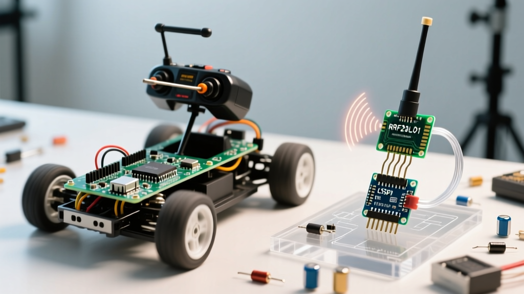
Wireless latency and sudden packet loss in an Arduino remote control car usually point to power rail collapse rather than code errors. The popular NRF24L01+ 2.4GHz transceiver draws peak currents of up to 120mA during transmission bursts. The Nordic Semiconductor nRF24L01+ specification sheet explicitly warns against high-impedance power sources. Most cheap Arduino Uno clones utilize the AMS1117-3.3 voltage regulator, which struggles to supply clean current past 150mA while managing thermal dissipation. When the radio transmits, the 3.3V rail sags below 1.9V, triggering an internal brownout reset in the RF module.
The Decoupling Capacitor Fix
To stabilize the RF module, solder a 10µF to 47µF electrolytic or tantalum capacitor directly across the VCC and GND pins of the NRF24L01+ breakout board. This local energy reservoir supplies the instantaneous 120mA spike without relying on the Arduino's long, high-resistance PCB traces. For HC-12 (433MHz) modules, which can draw up to 200mA during transmission, bypass the Arduino's regulator entirely and use a dedicated 3.3V buck converter (like the MP1584EN) fed directly from the main battery pack.
Joystick Drift and ADC Noise Filtering
A common complaint is the RC car 'creeping' forward or turning slightly when the transmitter joysticks are centered. The standard KY-023 joystick modules use 10kΩ carbon track potentiometers. These are highly susceptible to mechanical wear and electromagnetic interference (EMI) from nearby motor drivers. When you poll these pins using analogRead(), the Arduino ADC reference documentation notes that unshielded high-impedance analog inputs can easily pick up 10-20 LSBs of noise.
Implementing a Software Deadzone
Instead of relying purely on hardware filtering, implement a deadzone in your transmitter sketch. A centered joystick ideally reads 512 on a 10-bit ADC (0-1023). In your code, map any raw value between 485 and 535 directly to a 0 output. This 50-point buffer absorbs both the inherent potentiometer center-spring variance and the high-frequency EMI noise generated by the motor PWM signals.
Chassis Grounding and EMI Shielding
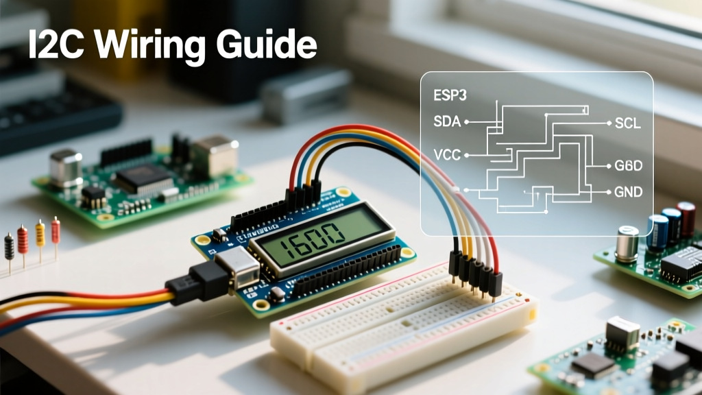
When scaling up to larger 4WD Arduino remote control car platforms, the physical wiring topology becomes just as critical as the schematic. High-current DC motors generate massive electromagnetic interference (EMI) and inductive voltage spikes during commutation. If your signal wires (like I2C lines for an MPU6050 gyroscope or SPI lines for the NRF24L01) are routed parallel to the motor power cables, the changing magnetic fields will induce parasitic voltages in the data lines. This manifests as random I2C bus lockups or corrupted RF payloads.
To mitigate this, enforce strict physical separation between high-current and low-current wiring. Route motor cables along the outer edges of the chassis, while keeping SPI/I2C data lines bundled tightly in the center. Furthermore, wrap your sensitive sensor modules in copper foil tape connected to a clean signal ground, creating a localized Faraday cage. For I2C buses, always use 4.7kΩ pull-up resistors on the SDA and SCL lines; the internal Arduino pull-ups (roughly 30kΩ to 50kΩ) are too weak to quickly pull the line high against capacitive load and EMI noise, leading to corrupted byte reads at 400kHz Fast Mode speeds.
Step-by-Step Diagnostic Flowchart
- Isolate the MCU: Disconnect the motor driver and RF module. Power the Arduino via USB. Upload a basic serial print sketch. If it runs flawlessly, your MCU and crystal oscillator are healthy.
- Load Test the Power Rail: Connect a multimeter to the 5V and 3.3V rails. Engage the motors and radio simultaneously via a test script. If the 3.3V rail dips below 3.1V, you have a regulator bottleneck requiring a dedicated LDO or buck converter.
- Check PWM Frequency: The default Arduino
analogWrite()runs at ~490Hz. This frequency can cause audible whining in DC motors and interfere with unshielded audio or sensor lines. Use theTCCR1Bregisters to shift the PWM frequency to 31kHz, moving the switching noise out of the audible and sensitive RF bands. - Verify Ground Topology: Ensure a 'star ground' topology. The high-current ground return from the motors must not share the same physical wire path as the low-current sensor/radio grounds before reaching the battery negative terminal. Shared ground paths introduce inductive voltage spikes that corrupt data lines.
FAQ: Edge Cases in Custom RC Builds
Why do my motors spin uncontrollably when the Arduino resets?
During a brownout reset, the Arduino's GPIO pins default to high-impedance (INPUT) states. If your motor driver's logic pins are left floating, stray EMI can trigger the H-bridge. Always use 10kΩ pull-down resistors on the IN1/IN2 pins of your motor driver to force a default LOW state during MCU reboots.
Can I use a single 9V alkaline battery for the motors and logic?
No. Standard 9V alkaline batteries have an internal resistance of roughly 1 to 2 ohms. Under a 500mA motor load, the voltage will instantly collapse below the Arduino's minimum operating threshold, causing continuous reboot loops. Use high-discharge 18650 Li-ion cells (like the Sony VTC6 or Samsung 25R) capable of sustaining 20A continuous draws without significant voltage sag.