
Why the Arduino Pro Micro for HID Projects?
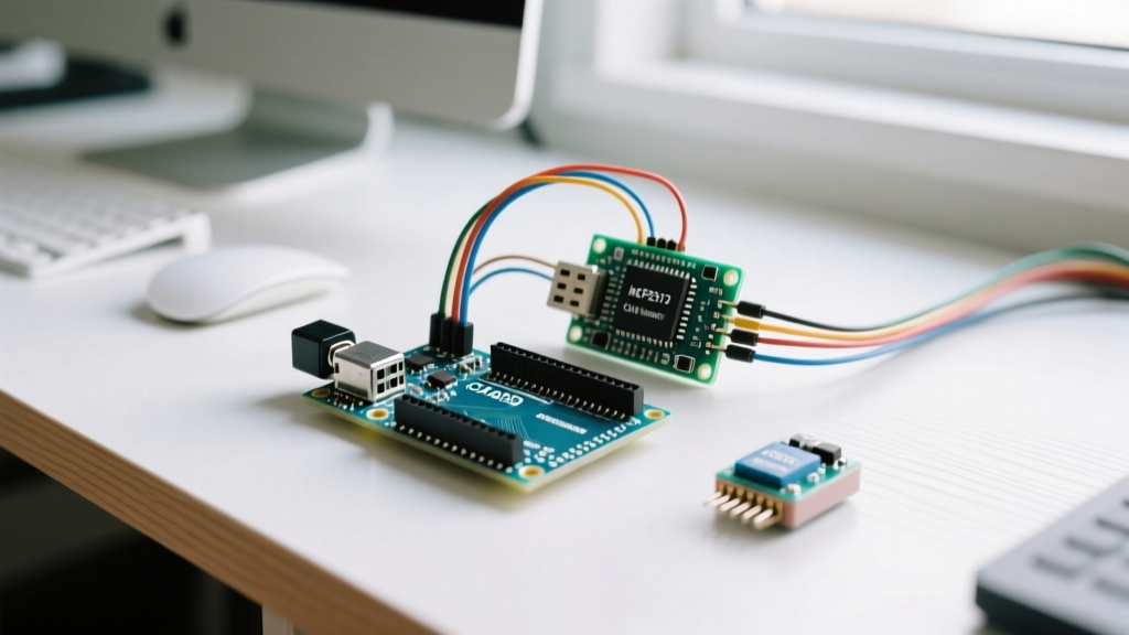
When building custom input devices like macro pads, split keyboards, or MIDI controllers, the Arduino Pro Micro is the undisputed champion of the maker community. Unlike the Arduino Uno or Nano, which rely on the ATmega328P microcontroller and require a secondary chip (like the ATmega16U2 or CH340) to translate serial data to USB, the Pro Micro is built around the ATmega32U4. This chip features native USB communication, allowing it to natively emulate Human Interface Devices (HID) such as keyboards, mice, and gamepads without any intermediary drivers on the host computer.
In this comprehensive guide, we will walk through the exact process of designing, wiring, and programming a 6-key custom macro pad using the Arduino Pro Micro. We will cover the critical hardware edge cases, matrix scanning logic, and how to avoid the infamous "bricked bootloader" scenario that plagues beginners.
Bill of Materials (BOM) & Component Selection
Choosing the right components is critical for a reliable HID device. Below is the recommended BOM for a 6-key (2x3 matrix) macro pad, with estimated 2026 market pricing.
| Component | Specification / Model | Estimated Cost | Notes |
|---|---|---|---|
| Microcontroller | SparkFun Pro Micro (5V/16MHz) | $18.50 (Clone: ~$6.00) | Must be 5V/16MHz for standard USB HID compliance. 3.3V variants often fail USB enumeration. |
| Switches | Cherry MX Brown or Gateron Yellow | $0.45 / ea | Mechanical switches provide the tactile feedback necessary for macro confirmation. |
| Diodes | 1N4148 DO-35 (Through-hole) | $0.02 / ea | Absolutely mandatory for matrix scanning to prevent ghosting. |
| Keycaps | DSA or XDA Profile (PBT) | $0.30 / ea | Uniform profiles are best for macro pads where finger reach varies. |
| Wiring | 22 AWG Solid Core Copper | $5.00 / spool | Stranded wire is too difficult to manage for hand-wired matrix columns. |
Understanding Keyboard Ghosting and the Diode Matrix
If you simply wire switches in a grid without diodes, you will encounter keyboard ghosting. Ghosting occurs when pressing three switches that form a rectangle on the matrix causes the controller to register a fourth "phantom" keypress at the empty corner of that rectangle. According to the Deskthority Keyboard Matrix Wiki, this happens because current flows backward through the unpressed switch, completing a circuit the microcontroller misinterprets.
To achieve N-Key Rollover (NKRO) and prevent ghosting, a 1N4148 signal diode must be placed in series with every single switch. The diode enforces a one-way current flow. When wiring, pay strict attention to the black band on the diode body. For a standard Row-to-Column scanning matrix, the black band (cathode) must point away from the switch and toward the column wire.
Step-by-Step Assembly Guide
- Prepare the Switches: Snap your 6 mechanical switches into your 3D-printed plate or acrylic sandwich case. Ensure the pins are perfectly straight; a bent pin will ruin the switch housing.
- Solder the Diodes: Bend the legs of the 1N4148 diodes. Solder the anode (no band) to the left pin of each switch. Solder the cathode (black band) to a continuous row wire made of 22 AWG solid copper. Repeat for all 6 switches, creating two distinct rows of 3 switches.
- Wire the Columns: Solder a separate wire to the right pin of each switch. These three wires will serve as your columns. Ensure no stray solder bridges the gap between the column wire and the row diode.
- Map to the Pro Micro: Solder your Row wires to digital pins
2and3. Solder your Column wires to digital pins4,5, and6. Avoid pins 0 and 1, as they are tied to the hardware serial TX/RX lines and can cause upload conflicts.
Arduino IDE Configuration & Edge Cases
Configuring the IDE for the Pro Micro can be notoriously frustrating due to the prevalence of overseas clone boards. The official SparkFun Pro Micro Hookup Guide recommends adding the SparkFun board manager URL to your IDE preferences. However, if you are using a generic clone, you will often find success by simply selecting "Arduino Leonardo" from the default board list, as the Leonardo shares the exact same ATmega32U4 architecture and bootloader.
Critical Warning: 5V vs 3.3V Logic Levels. USB data lines (D+ and D-) require 3.3V logic, which the Pro Micro handles via an onboard regulator. However, if you purchase a 3.3V/8MHz Pro Micro, the Keyboard.h library timing may fail because the library is calibrated for a 16MHz clock speed. Always purchase the 5V/16MHz variant for HID projects.
Firmware: Scanning the Matrix
Below is the optimized C++ firmware for our 2x3 matrix. This code utilizes the internal pull-up resistors of the ATmega32U4, eliminating the need for external resistors on the column lines. For deeper understanding of the HID functions, refer to the official Arduino Keyboard Library Reference.
#include <Keyboard.h>

// Matrix dimensions
const int ROWS = 2;
const int COLS = 3;

// Pin assignments
int rowPins[ROWS] = {2, 3};
int colPins[COLS] = {4, 5, 6};

// Keymap (Customize these HID codes to your needs)
char keyMap[ROWS][COLS] = {
  {KEY_LEFT_CTRL, 'c', 'v'},
  {KEY_LEFT_GUI, 'z', KEY_RETURN}
};

bool keyState[ROWS][COLS] = {false};
unsigned long lastDebounceTime = 0;
const long debounceDelay = 5; // 5ms debounce

void setup() {
  for (int r = 0; r < ROWS; r++) {
    pinMode(rowPins[r], OUTPUT);
    digitalWrite(rowPins[r], HIGH);
  }
  for (int c = 0; c < COLS; c++) {
    pinMode(colPins[c], INPUT_PULLUP);
  }
  Keyboard.begin();
}

void loop() {
  if ((millis() - lastDebounceTime) > debounceDelay) {
    for (int r = 0; r < ROWS; r++) {
      digitalWrite(rowPins[r], LOW); // Pulse row LOW
      for (int c = 0; c < COLS; c++) {
        bool currentRead = !digitalRead(colPins[c]); // Active LOW
        if (currentRead != keyState[r][c]) {
          keyState[r][c] = currentRead;
          if (currentRead) {
            Keyboard.press(keyMap[r][c]);
          } else {
            Keyboard.release(keyMap[r][c]);
          }
        }
      }
      digitalWrite(rowPins[r], HIGH); // Reset row
    }
    lastDebounceTime = millis();
  }
}
Advanced: Power Delivery and Voltage Regulator Bypass
If you intend to build a wireless macro pad using a 3.7V LiPo battery and a Bluetooth module (like the Adafruit Feather 32u4 Bluefruit LE), the standard Pro Micro's onboard MIC5219 voltage regulator will introduce unnecessary voltage drop and quiescent current drain. Advanced makers often carefully desolder or clip the voltage regulator and bypass the RAW pin directly to the VCC pin, feeding the ATmega32U4 a clean 3.3V from an external low-dropout (LDO) regulator or battery management system. This reduces idle power consumption by up to 40%, extending battery life significantly in portable HID builds.
Troubleshooting: Unbricking the Bootloader
The most common failure mode when programming native USB HID devices is uploading a sketch that spams keystrokes or crashes the USB stack immediately upon boot. When this happens, the host computer cannot establish a serial connection, and the Arduino IDE will throw an "Upload timeout" or "Board not found" error.
The Double-Tap Reset Fix:
- Locate the
RST(Reset) andGND(Ground) pins on the Pro Micro. - Prepare a jumper wire connected to GND.
- Click the "Upload" button in the Arduino IDE.
- The moment the IDE console says "Uploading...", quickly tap the jumper wire to the RST pin twice in rapid succession.
- This forces the ATmega32U4 into its 8-second bootloader mode, bypassing the broken sketch and allowing the new, safe firmware to flash.
By mastering the hardware nuances of the Arduino Pro Micro and the logic of diode-based matrix scanning, you can build highly responsive, ghost-free macro pads that rival commercial $200+ programmable keypads on the market.