
The Anatomy of Arduino Power Failures
Random microcontroller resets, fading status LEDs, corrupted EEPROM data, and failed sketch uploads are the most frustrating issues in embedded prototyping. In 90% of cases, these anomalies trace back to an inadequate or failing arduino power source. The ATmega328P and modern ARM-based MCUs are highly sensitive to voltage sags, high-frequency ripple, and thermal throttling on the regulation stage.
Understanding the exact failure modes of your board's power delivery network (PDN) is critical. This guide bypasses generic advice and dives deep into the electrical realities of Arduino power architectures, providing exact multimeter testing protocols, component-level failure analysis, and definitive hardware fixes for 2026 maker setups.
Diagnostic Matrix: Symptoms vs. Power Culprits
Before grabbing a soldering iron, map your specific symptom to the likely point of failure in the power delivery chain.
| Observed Symptom | Probable Power Source Culprit | Quick Diagnostic Test |
|---|---|---|
| Resets exactly when a servo or relay actuates | Voltage sag on the 5V rail exceeding the Brown-out Detection (BOD) threshold. | Measure the 5V pin with a DMM in Min/Max mode during actuation. |
| Sketch upload fails at 40-60% completion | USB VBUS dropping below 4.75V due to cable resistance or hub starvation. | Swap to a sub-1-meter 22AWG USB cable; bypass unpowered hubs. |
| Board is hot to the touch; resets after 5 minutes | Linear regulator thermal shutdown due to high Vin and high current draw. | Check Vin at the barrel jack; calculate thermal dissipation. |
| Serial monitor outputs garbage characters randomly | High-frequency switching noise or ripple on the VCC rail corrupting the UART clock. | Inspect ripple with an oscilloscope; add high-frequency decoupling caps. |
Failure Mode 1: Barrel Jack Thermal Throttling
The classic Arduino Uno R3 utilizes an NCP1117ST50T3G linear voltage regulator to step down the barrel jack input (recommended 7-12V) to a stable 5V. While 12V is technically within the 'recommended' limit printed on the silkscreen, it is a thermal trap for high-current projects.
The Thermal Math
If you power your board with a 12V wall adapter and your circuit (e.g., an LED matrix or multiple sensors) draws 500mA from the 5V rail, the linear regulator must dissipate the excess voltage as heat. The power dissipated ($P_D$) is calculated as:
P_D = (Vin - Vout) * I = (12V - 5V) * 0.5A = 3.5 Watts
The SOT-223 package of the NCP1117 has a junction-to-ambient thermal resistance ($\theta_{JA}$) of approximately 100°C/W. A 3.5W dissipation results in a junction temperature rise of 350°C above ambient. Because the regulator features internal thermal shutdown at roughly 155°C, it will rapidly overheat, shut off the 5V rail, cool down, and restart—causing a continuous boot-loop that looks like a software crash.
The Definitive Fix
- Low Current (<100mA): Keep the 12V input. The dissipation will be under 0.7W, which the SOT-223 package can handle passively.
- High Current (>200mA): Drop your barrel jack input voltage to 7.5V. This reduces the voltage drop across the regulator to 2.5V, cutting heat generation by more than half.
- The Pro Fix: Abandon the onboard linear regulator entirely. Purchase an LM2596 or MP1584EN step-down buck converter module ($3 to $6 online). Set the potentiometer to output exactly 5.0V, and feed this directly into the Arduino's
5Vpin. Switching regulators operate at 85-90% efficiency, virtually eliminating heat generation even at 2A loads.
For a deeper understanding of how these linear components manage heat and dropout voltages, refer to the SparkFun Voltage Regulator Tutorial, which details the physical limitations of linear versus switching architectures.
Failure Mode 2: USB VBUS Voltage Drop
When powered via USB, the Arduino relies on the host PC's 5V VBUS line. The ATmega328P requires a minimum of 4.5V to operate reliably at 16MHz. If the voltage dips below this threshold, the MCU's internal brown-out detection triggers a reset.
The AWG Cable Problem
Cheap, mass-produced USB cables often use 28AWG or even 30AWG wire for the power lines. A standard 2-meter 28AWG copper cable has a resistance of roughly 0.7 Ohms round-trip. If your Arduino and attached shields draw 500mA, Ohm's Law dictates a voltage drop of 0.35V across the cable alone. Add the voltage drop across the Arduino's onboard Schottky diode and polyfuse, and your MCU is seeing less than 4.4V—guaranteeing instability.
The Fix
- Upgrade the Cable: Purchase a premium USB cable rated for fast charging, which typically utilizes 22AWG or 20AWG power conductors. Keep the length under 1 meter for high-current setups.
- Bypass Hubs: Unpowered USB hubs often sag to 4.6V under load. Plug the Arduino directly into the motherboard's rear I/O panel, which is soldered directly to the PC's primary ATX power supply rails.
Failure Mode 3: LiPo Battery Sag and BOD Resets
Portable projects frequently use a 3.7V LiPo battery connected to the RAW or VIN pin of an Arduino Pro Mini or Nano. When integrating RF modules like the nRF24L01+ or GSM shields, the radio can draw instantaneous current spikes of 1.2A during transmission bursts.
A standard 1000mAh LiPo cell has an internal resistance (ESR) that causes the terminal voltage to momentarily collapse under these spikes. If the voltage drops below the default Brown-out Detection (BOD) fuse setting of 2.7V, the microcontroller resets. Worse, if the voltage hovers right at the edge of the BOD threshold during an EEPROM write operation, the memory map can become permanently corrupted.
Hardware and Firmware Mitigations
- Capacitor Buffering: Solder a 100µF to 470µF low-ESR tantalum capacitor directly across the VCC and GND pins of the RF module, not just at the Arduino's main power rails. This provides localized charge storage for microsecond transmission spikes.
- Lower the BOD Threshold: Using an ISP programmer (like a USBasp), re-flash the ATmega328P bootloader fuses to lower the BOD from 2.7V to 1.8V. This prevents the chip from resetting during temporary RF voltage sags, though it requires careful code management to avoid EEPROM corruption.
- Use a High-Discharge Cell: Swap standard LiPo pouches for 18650 Lithium-Ion cells rated for 15A+ continuous discharge (e.g., Samsung 25R or Sony VTC6). Their vastly lower internal resistance virtually eliminates transient voltage sag.
Advanced Hardware Bypasses (With Safety Warnings)
CRITICAL WARNING: Backfeeding 5V directly into the Arduino's
5Vheader pin bypasses the onboard polyfuse and reverse-polarity protection diode. If your external power supply drifts above 5.5V, or if you accidentally plug in 9V, you will instantly destroy the ATmega16U2 USB interface chip and the main microcontroller. Only use this method with highly regulated, over-voltage-protected bench supplies or premium buck converters.
For advanced users building custom shields or permanent installations, bypassing the onboard USB and barrel jack circuitry entirely is the gold standard for power reliability. By injecting clean, regulated 5V directly into the 5V pin, you eliminate the forward voltage drop (typically 0.3V) of the M7 Schottky diode and the resistance of the 500mA resettable PTC polyfuse. This ensures the MCU receives the full, unadulterated 5.0V from your external supply.
Essential Multimeter Testing Protocol
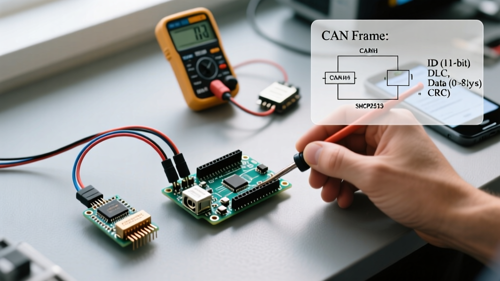
To definitively diagnose your arduino power source, you must move beyond static voltage checks. Follow this dynamic testing protocol:
- Set your DMM to DC Voltage (Min/Max mode): Standard multimeters average readings over 400ms, completely missing microsecond voltage sags caused by motor brushes or RF spikes. Min/Max mode captures the absolute lowest voltage dip.
- Probe at the MCU, not the pins: Place your red probe directly on the VCC trace near the ATmega328P IC, and the black probe on the nearest GND plane. Measuring at the edge of the header pins ignores voltage drops across the PCB traces themselves.
- Trigger the Load: Run a stress-test sketch that toggles all output pins HIGH, activates attached relays, and fires RF transmissions simultaneously while monitoring the Min/Max voltage on your meter.
For comprehensive schematics and official power delivery specifications across different board revisions, always consult the official Arduino Uno Rev3 Documentation. Understanding the exact pathways of the VBUS, VIN, and 5V rails on your specific board revision is the first step toward bulletproof project reliability.