
The Hidden Dangers of Inductive Loads
Integrating an arduino electromagnet into a DIY project—whether for a custom solenoid lock, a magnetic actuator, or an automated sorting mechanism—is a rite of passage for makers. However, electromagnets are fundamentally inductive loads. Unlike simple resistive components (like LEDs or heaters), inductors resist changes in current. When you abruptly cut power to an electromagnet, the collapsing magnetic field generates a massive reverse voltage spike known as Back-EMF (Electromotive Force).
If your circuit is not properly designed to handle this inductive kickback, you will experience a cascade of frustrating errors: random microcontroller resets, melted transistors, or permanently bricked ATmega328P I/O pins. According to All About Circuits, inductive spikes from a simple 12V relay or electromagnet can easily exceed 100V, far beyond the 5.5V absolute maximum rating of an Arduino Uno's logic pins.
This guide provides a deep-dive diagnostic matrix to identify, isolate, and resolve the five most common hardware and code-level errors when driving electromagnets with an Arduino in 2026.
Diagnostic Matrix: Symptom to Root Cause
| Observed Symptom | Probable Root Cause | Quick Diagnostic Test |
|---|---|---|
| Arduino resets instantly when electromagnet triggers. | Back-EMF spike causing brown-out or I/O pin injection. | Disconnect electromagnet; trigger MOSFET via code. If Arduino stays on, it is an inductive kickback issue. |
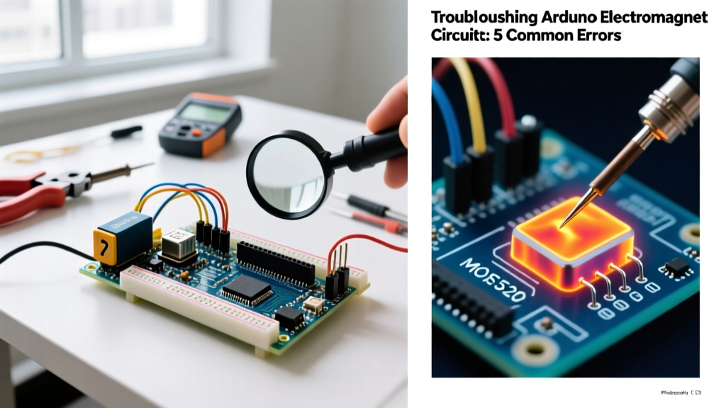
| Switching transistor becomes too hot to touch. | Using a standard MOSFET (e.g., IRF520) instead of a logic-level MOSFET. | Measure voltage drop across Drain-Source while active. High drop indicates linear region operation. |
| Electromagnet pull force is extremely weak. | Insufficient current delivery from power supply or USB rail. | Measure voltage at the electromagnet terminals under load. Look for severe voltage sag. |
| MOSFET instantly explodes or shorts upon activation. | Flyback diode installed backward, creating a dead short. | Check diode band (cathode). It must face the positive voltage rail. |
| Electromagnet hums or stays partially engaged during PWM. | Incorrect PWM frequency or slow diode recovery time. | Verify PWM pin and check if using a standard 1N4007 instead of a fast Schottky diode. |
Error 1: The 'Arduino Reset Loop' (Back-EMF Injection)
The Physics of the Failure
The formula for inductive voltage is V = -L(di/dt). When your Arduino sets the gate pin to LOW, the MOSFET turns off in nanoseconds. The time delta (dt) approaches zero, causing the voltage (V) to spike toward infinity. This spike travels backward through the circuit. If it reaches the Arduino's 5V rail, it triggers the ATmega328P's internal Brown-Out Detector (BOD), causing an immediate reset. If it enters the I/O pin directly, it destroys the silicon junction.
The Fix: Proper Flyback Diode Placement
You must install a flyback diode in parallel with the electromagnet coil. As of 2026, the 1N4007 (rated for 1000V, 1A) remains the standard for low-frequency on/off switching, costing roughly $0.05 per unit. For high-frequency PWM applications, upgrade to a 1N5819 Schottky diode ($0.15) to avoid reverse-recovery time issues.
Critical Wiring Rule: The diode's cathode (the end with the silver stripe) MUST connect to the positive supply voltage. The anode connects to the MOSFET's drain. Reversing this creates a direct short circuit the moment the MOSFET turns on, instantly vaporizing your transistor.
Error 2: The IRF520 Overheating Trap
A pervasive mistake in maker communities is purchasing cheap 'MOSFET Driver Modules' that utilize the IRF520. The IRF520 is a standard MOSFET, not a logic-level MOSFET. It requires a Gate-to-Source voltage ($V_{GS}$) of 10V to fully open its channel and achieve its rated low On-Resistance ($R_{DS(on)}$).
An Arduino Uno outputs a maximum of 5V on its digital pins. At 5V, the IRF520 only partially opens, operating in its linear (resistive) region. If your electromagnet draws 3 Amps, the partially open IRF520 will dissipate massive amounts of heat ($P = I^2R$), leading to thermal runaway and component failure.
Component Selection: BJT vs. Standard vs. Logic-Level
| Component | Type | Arduino 5V Compatible? | Voltage Drop / Heat | 2026 Avg. Price |
|---|---|---|---|---|
| TIP120 | Darlington BJT | Yes | High (~2.0V Vce drop, requires heatsink for >1A) | $0.85 |
| IRF520 | Standard MOSFET | No (Needs 10V Gate) | Severe (Operates in linear region at 5V) | $0.50 |
| IRLZ44N | Logic-Level MOSFET | Yes (Fully on at 5V) | Negligible ($R_{DS(on)}$ = 22mΩ at 5V) | $1.80 |
| IRLB8721 | Logic-Level MOSFET | Yes (Optimized for 4.5V) | Extremely Low (Ideal for high current) | $2.10 |
Expert Recommendation: Discard IRF520 modules. Replace them with a through-hole IRLZ44N or an IRLB8721. According to the SparkFun Transistor Tutorial, ensuring your $V_{GS(th)}$ (Gate Threshold Voltage) is well below your microcontroller's logic HIGH voltage is mandatory for efficient switching.
Error 3: Weak Magnetic Pull (Power Supply Starvation)
If your electromagnet clicks but lacks the force to pull its armature, you are likely experiencing voltage sag due to inadequate current sourcing. A typical 12V, 10W electromagnet has a coil resistance of roughly 14.4 Ohms and draws ~0.83 Amps.
Common Power Mistakes
- Powering via Arduino Vin/5V Pin: The Arduino's onboard linear regulator will overheat and shut down at currents above 200mA. Never route electromagnet power through the Arduino PCB.
- Using 9V Alkaline Batteries: Standard 9V batteries have a high internal resistance and cannot sustain the 1A+ burst current required by inductive loads. The voltage will instantly collapse to 4V under load.
The Fix: Dedicated Switched-Mode Power Supplies
Use a dedicated 12V DC power supply. The Mean Well LRS-35-12 (35W, 12V, 3A) is the industry standard for maker enclosures in 2026, priced around $16. Connect the power supply's ground (GND) directly to the Arduino's GND to establish a common reference voltage for the MOSFET gate signal.
Error 4: Flyback Diode Failures and Snubber Networks
Even with a diode installed, you might still experience localized EMI (Electromagnetic Interference) that disrupts sensitive sensors (like I2C OLED displays or analog load cells) connected to the same Arduino.
When to Use an RC Snubber
A standard flyback diode clamps the reverse voltage to roughly 0.7V above the supply rail, which is safe for the MOSFET. However, it allows the coil current to decay slowly, which can cause the electromagnet to 'stick' or release sluggishly. If your application requires rapid, precise release times (such as a high-speed sorting actuator), add an RC Snubber network in series with the flyback diode.
A typical snubber for a 12V electromagnet consists of a 47 Ohm resistor and a 0.1µF ceramic capacitor in series, placed in parallel with the coil. This dissipates the inductive energy as heat in the resistor rather than recirculating it through the coil, resulting in a crisp, instantaneous mechanical release.
Error 5: Code-Level Timing and PWM Errors
Sometimes the hardware is flawless, but the Arduino sketch introduces errors. If you are using PWM (Pulse Width Modulation) via the analogWrite() function to proportionally control the electromagnet's force, you must account for the Arduino's default PWM frequency.
On an Arduino Uno, pins 5 and 6 operate at ~980 Hz, while pins 9, 10, 11, and 3 operate at ~490 Hz. Driving an inductive load at 490 Hz with a standard 1N4007 diode can cause the diode to fail to recover in time, leading to excessive heat in the MOSFET.
Software Fix: Altering Timer Registers
You can increase the PWM frequency on pins 9 and 10 to ~31.25 kHz by modifying Timer1 in your setup() function:
TCCR1B = TCCR1B & B11111000 | B00000001;
This high-frequency switching eliminates audible whining from the electromagnet coil and ensures the inductive current remains relatively continuous, providing a smoother, more predictable magnetic force. For deeper insights into microcontroller timer manipulation, refer to the Arduino Official Transistor and Motor Documentation.
Final Diagnostic Checklist
Before applying power to your next arduino electromagnet build, verify these four physical checkpoints:
- Is the load power supply completely separate from the Arduino's 5V logic rail?
- Is a common ground established between the Arduino GND and the Power Supply GND?
- Is a logic-level MOSFET (IRLZ44N/IRLB8721) being used instead of an IRF520 or TIP120?
- Is the flyback diode oriented correctly (cathode stripe pointing to the positive rail)?
By respecting the physics of inductive loads and selecting the correct logic-level switching components, you will eliminate 99% of the hardware failures associated with DIY magnetic actuators.