
Introduction to the Arduino Portenta Machine Control
The Arduino Portenta Machine Control (PMC) represents a paradigm shift in industrial edge computing, bridging the gap between rapid prototyping and ruggedized, IEC 61131-3 compliant PLC environments. Priced around $390 USD in 2026, the PMC is built upon the Portenta H7 architecture, leveraging a dual-core STMicroelectronics STM32H747XI microcontroller (Cortex-M7 at 480MHz and Cortex-M4 at 240MHz). Unlike standard development boards, the PMC integrates essential industrial interfaces natively: 24V digital I/O, 4-20mA analog inputs, thermocouple amplifiers, and isolated RS-485/CAN buses.
In this comprehensive tutorial, we will walk through the exact hardware wiring, jumper configurations, and C++ programming required to deploy the PMC in a real-world industrial scenario. Specifically, we will wire a 24V power supply, read a 4-20mA pressure transmitter, and trigger a 24V digital output relay based on a threshold. For foundational architecture details, refer to the official Arduino Portenta Machine Control Getting Started Guide.
Hardware Prerequisites and Bill of Materials
Before writing a single line of code, you must assemble an industrial-grade test bench. The PMC is not designed for 5V USB power in deployment; it requires a stable 24V DC industrial supply.
- Microcontroller: Arduino Portenta Machine Control (SKU: ABX00061 or newer 2026 revisions).
- Power Supply: Mean Well HDR-30-24 (24V DC, 1.5A, DIN-rail mount) - approx. $35 USD.
- Sensor: Industrial 4-20mA Pressure Transmitter (e.g., 0-100 PSI, 2-wire loop-powered).
- Actuator: 24V DC Ice Cube Relay with flyback diode protection.
- Cabling: 18 AWG stranded wire, ferrule crimps, and M12 A-coded cordsets for Ethernet/sensors.
- Software: Arduino IDE 2.3+ or VS Code with PlatformIO.
Wiring the 24V Power and Digital I/O
The PMC utilizes a heavy-duty 24-pin front-facing terminal block for primary power and digital I/O. Incorrect wiring here can permanently damage the internal optocouplers or the high-side switch ICs.
Power and Ground Connections
The board accepts 24V DC (or AC) on pins 1 and 2. Ground connections are located on pins 23 and 24. Always use ferrule crimps on your 18 AWG stranded wires to prevent stray strands from causing short circuits between the 24V and GND terminals.
Digital Output Wiring (Sourcing)
The PMC features 10 digital outputs (DO0 to DO9). These are high-side sourcing switches. This means the PMC provides the +24V to the load when activated, and your load must be connected to the system ground externally. Each channel can handle up to 2A, with a total board limit of 10A.
Expert Warning: If you are driving inductive loads like solenoid valves or raw relay coils, you must install a flyback diode (e.g., 1N4007) in reverse parallel across the load. The PMC's internal TVS diodes will eventually fail under repeated inductive kickback spikes exceeding 35V.
Configuring Analog Inputs for 4-20mA Loops
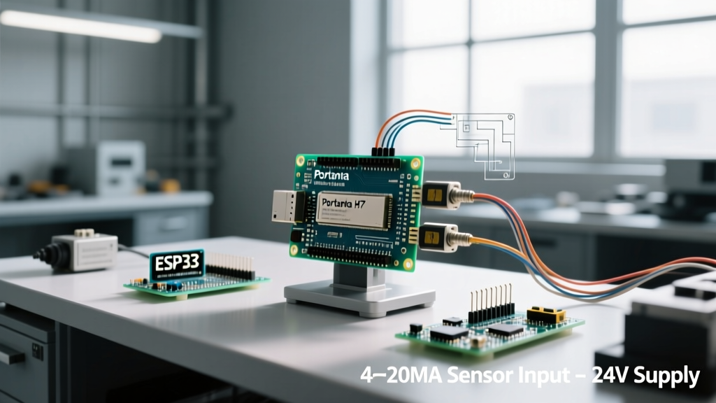
The PMC offers three analog input channels (AI0, AI1, AI2) capable of reading both 0-10V and 4-20mA signals. However, the board does not auto-detect the signal type. To read a 4-20mA loop, a precision 120-ohm shunt resistor must be switched into the circuit to convert the current into a measurable voltage (0.48V to 2.4V) for the internal 12-bit ADC.
On earlier PMC revisions, this required opening the extruded aluminum enclosure and moving SMD jumpers (JP1, JP2, JP3). On the latest 2026 hardware revisions, this is managed via software-controlled solid-state relays or external DIP switches accessible via a side panel. Always verify your specific board revision's schematic on the Arduino MachineControl GitHub Repository before applying power to a current loop.
Wiring the 2-Wire 4-20mA Transmitter
- Connect the 24V+ from your power supply to the positive terminal of the pressure transmitter.
- Connect the negative (signal) terminal of the transmitter to the AI0 terminal on the PMC.
- Ensure the PMC's GND (Pin 23/24) shares a common ground reference with the 24V power supply's negative terminal to complete the loop.
Arduino IDE Configuration and Library Setup
To program the STM32H747XI core inside the PMC, you must install the correct board definitions.
- Open the Arduino IDE and navigate to Boards Manager.
- Search for and install Arduino Mbed OS Portenta Boards (ensure you are on version 4.x or newer for 2026 compatibility).
- Navigate to Library Manager and install the Arduino_MachineControl library. This library abstracts the complex I2C multiplexing required to communicate with the onboard I/O expanders and ADCs.
- Select Tools > Board > Arduino Mbed OS Portenta Boards > Arduino Portenta H7.
- Select Tools > Flash Split > 1MB M7 + 1MB M4 (or 2MB M7 if you are not using the M4 core for parallel DSP tasks).
C++ Implementation: Reading 4-20mA and Triggering Relays
Below is the production-ready C++ sketch. This code initializes the PMC, reads the current from AI0 (mapped to a 0-100 PSI pressure scale), and triggers Digital Output 0 if the pressure exceeds 75 PSI.
#include <Arduino_MachineControl.h>

using namespace machinecontrol;

// Configuration constants
const float MIN_PSI = 0.0;
const float MAX_PSI = 100.0;
const float THRESHOLD_PSI = 75.0;
const int RELAY_PIN = 0; // DO0
const int ANALOG_CHANNEL = 0; // AI0

void setup() {
  Serial.begin(115200);
  while (!Serial) { delay(10); }

  // Initialize the PMC hardware controllers
  if (!MachineControl.begin()) {
    Serial.println("PMC Initialization Failed! Check I2C lines.");
    while (1) { delay(1000); }
  }

  // Ensure all digital outputs are LOW on boot
  DigitalOutputs.setAll(0);
  Serial.println("Arduino Portenta Machine Control Ready.");
}

void loop() {
  // Read the raw current in milliamps (4.0 to 20.0 mA)
  float current_mA = AnalogIn.readCurrent(ANALOG_CHANNEL);

  // Map the 4-20mA signal to our 0-100 PSI sensor range
  float pressure_PSI = map(current_mA, 4.0, 20.0, MIN_PSI, MAX_PSI);

  // Handle edge cases: Wire break (current < 3.8mA) or short circuit
  if (current_mA < 3.8) {
    Serial.println("ERROR: Sensor wire break detected (< 3.8mA)!");
    DigitalOutputs.write(RELAY_PIN, LOW); // Fail-safe: turn off
  } else if (current_mA > 21.0) {
    Serial.println("ERROR: Sensor short circuit detected (> 21.0mA)!");
  } else {
    Serial.print("Pressure: ");
    Serial.print(pressure_PSI);
    Serial.println(" PSI");

    // Control logic
    if (pressure_PSI >= THRESHOLD_PSI) {
      DigitalOutputs.write(RELAY_PIN, HIGH); // Trigger alarm/valve
    } else {
      DigitalOutputs.write(RELAY_PIN, LOW);
    }
  }

  delay(500); // 2Hz polling rate
}
PMC I/O Pinout and Capability Matrix
Understanding the exact electrical limits of the PMC prevents catastrophic field failures. Refer to the matrix below when designing your control panels.
| Interface | Channels | Voltage / Range | Max Current / Limit | Isolation |
|---|---|---|---|---|
| Digital Inputs | 8 (DI0-DI7) | 24V DC (Logic 1 > 10V) | 15 mA max per pin | Optocoupled (Internal) |
| Digital Outputs | 10 (DO0-DO9) | 24V DC Sourcing | 2A per ch / 10A total | High-side switch IC |
| Analog Inputs | 3 (AI0-AI2) | 0-10V or 4-20mA | 12-bit ADC (4096 steps) | Shared GND (No Galvanic) |
| Thermocouple | 3 (TC0-TC2) | Type K / J / PT100 | Max 400°C (Type K) | Galvanic via SPI ISO |
| RS-485 / CAN | 1 Shared Port | Up to 1 Mbps | 120-ohm term. jumper | Galvanic Isolation (2.5kV) |
Troubleshooting Edge Cases and Failure Modes
Deploying the STM32H747XI-based PMC in noisy industrial environments introduces specific failure modes that do not occur on a lab bench.
1. Floating Analog Inputs and Noise
If an analog input channel (e.g., AI1) is left unconnected while reading AI0, the internal ADC multiplexer can experience charge injection, causing phantom voltage readings on AI0. Solution: Always terminate unused analog input terminals to GND using a short jumper wire, or configure the software to ignore and bypass reading those specific channels in the Mux sequence.
2. Ground Loops on 4-20mA
Because the PMC's analog inputs are not galvanically isolated from the main 24V DC ground, connecting a sensor powered by a separate, distant 24V supply can create a ground loop. This manifests as a 50/60Hz hum or a static offset in your 4-20mA reading. Solution: Use a single, centralized 24V power supply for both the PMC and the 2-wire loop sensors. If distant power is mandatory, insert a 4-20mA galvanic isolator module between the sensor and the PMC AI terminal.
3. Watchdog Timer (WDT) Resets
In mission-critical deployments, a hung I2C bus (which the PMC uses to talk to its I/O expanders) can freeze the main loop. The Mbed OS core includes a hardware watchdog. Implement the mbed::Watchdog class in your sketch to automatically hard-reset the Cortex-M7 core if the loop stalls for more than 2 seconds, ensuring the factory line doesn't halt due to a transient EMI spike.
Conclusion
The Arduino Portenta Machine Control eliminates the need for bulky, proprietary PLC hardware in mid-tier automation tasks. By respecting its electrical boundaries—specifically the high-side nature of its digital outputs and the jumper-dependent 4-20mA configurations—you can deploy robust, C++-driven edge control systems that rival traditional ladder-logic controllers in both speed and flexibility.