
The Headless Shift: Moving Beyond the Desktop IDE
As edge computing matures in 2026, the paradigm of tethering a laptop to a microcontroller for every code change is becoming obsolete for serious makers and industrial prototypers. Integrating an Arduino in Raspberry Pi deployments creates a powerful hybrid topology: the Pi handles high-level networking, computer vision, and database logging, while the Arduino manages deterministic, real-time I/O and hardware interrupts. However, optimizing this workflow requires abandoning the traditional Arduino IDE in favor of headless toolchains, robust serial protocols, and careful power management.
This guide details how to streamline your development pipeline using the Arduino CLI, solve the notorious DTR auto-reset edge case, and design a resilient hardware topology that prevents brownouts and logic-level failures.
Deploying the Arduino CLI on Raspberry Pi OS
The Arduino CLI is the cornerstone of a headless workflow. It allows you to compile, upload, and manage board packages directly from the Raspberry Pi terminal or via automated bash scripts. On a Raspberry Pi 5 running the 64-bit Bookworm OS, installation takes seconds.
Installation and Configuration
Instead of downloading the GUI, use the official install script to grab the latest ARM64 binary:
curl -fsSL https://raw.githubusercontent.com/arduino/arduino-cli/master/install.sh | sh
./bin/arduino-cli config init
./bin/arduino-cli core update-index
./bin/arduino-cli core install arduino:renesas_uno
Once installed, you can compile and flash an Arduino Uno R4 Minima directly over USB without a monitor attached. A standard build-and-flash script looks like this:
#!/bin/bash
# build_and_flash.sh
SKETCH='/home/pi/edge-sensors/main.ino'
PORT='/dev/ttyACM0'
FQBN='arduino:renesas_uno:minima'

./bin/arduino-cli compile --fqbn $FQBN $SKETCH
./bin/arduino-cli upload -p $PORT --fqbn $FQBN $SKETCHHardware Topologies: USB CDC vs. I2C vs. UART
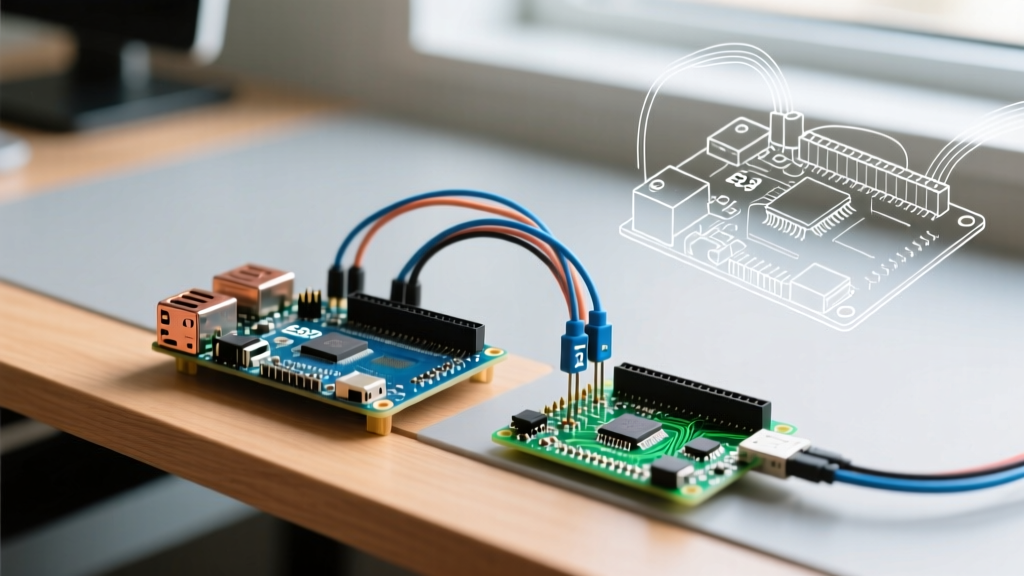
Choosing how the Pi and Arduino communicate dictates your latency, wiring complexity, and CPU overhead. Below is a comparison matrix for the three most common interfaces used in an Arduino in Raspberry Pi setup.
| Protocol | Max Speed (Practical) | Wiring Complexity | Best Use Case | Edge Case / Limitation |
|---|---|---|---|---|
| USB CDC (Serial) | 1 Mbps (Uno R4) | Low (Single USB Cable) | Telemetry, JSON payloads, OTA updates | DTR auto-reset triggers on port open |
| I2C (Multi-Master) | 400 kHz (Fast Mode) | Medium (Requires Logic Shifting) | High-frequency sensor polling, state sync | Pi is strictly master; clock stretching issues |
| UART (GPIO Pins) | 115,200 bps (Standard) | Medium (TX/RX + GND) | Low-latency command/response, no USB reset | Requires disabling Pi serial console in raspi-config |
For most 2026 edge deployments, USB CDC remains the most popular due to the ease of power delivery and high baud rates (the Renesas RA4M1 on the Uno R4 easily handles 1,000,000 baud). However, it introduces a critical hardware edge case that ruins headless workflows.
The DTR Auto-Reset Edge Case (And How to Fix It)
When your Python or Node.js script on the Raspberry Pi opens the /dev/ttyACM0 serial port, the underlying TTY driver often asserts the DTR (Data Terminal Ready) line. On classic AVR Arduinos and the newer Uno R4, the DTR line is coupled through a 0.1µF capacitor directly to the MCU's RESET pin.
The Result: Every time your Pi script restarts or opens the port, the Arduino reboots. In a headless environment, this destroys sensor state, interrupts PID loops, and causes missed data packets.
Three Solutions for Headless Stability
- Software (Python pyserial): Explicitly disable DTR and RTS assertions when initializing the port. Note that Linux TTY drivers sometimes ignore this flag, making it unreliable on its own.
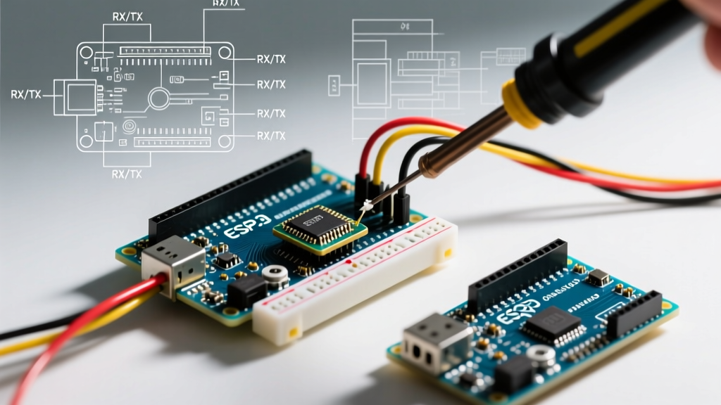
import serial ser = serial.Serial('/dev/ttyACM0', 1000000, dsrdtr=False, rts=False) - Hardware (The Capacitor Trick): Solder a 10µF electrolytic capacitor between the
RESETandGNDpins on the Arduino. This absorbs the brief DTR pulse, preventing the MCU from resetting while still allowing the Pi to flash new firmware via the Arduino CLI (which uses a specific 1200-bps baud rate toggle to trigger the bootloader). - Alternative Hardware: Use the Arduino Nano ESP32 ($22). Its USB implementation uses a native USB peripheral rather than a CDC-ACM bridge tied to the reset circuit, completely eliminating the DTR reboot issue.
Power Delivery and Logic Level Shifting
According to the official Raspberry Pi hardware documentation, the Raspberry Pi 5 can deliver up to 1.6A across all USB ports combined, provided you are using the official 27W USB-C PD power supply. While this sounds sufficient, real-world transient spikes tell a different story.
The Wi-Fi Brownout Failure Mode
If your workflow utilizes an Arduino Nano ESP32 or a Nano 33 IoT, transmitting data over Wi-Fi or BLE can cause current spikes of up to 350mA. If you also have a USB LiDAR sensor or webcam connected to the Pi, the total current draw will exceed the Pi's internal USB polyfuse limits. The Pi's kernel will log over-current errors in dmesg, and the Arduino will brownout, dropping the serial connection.
Expert Fix: Decouple the power tree. Use a Pololu D24V50F5 step-down buck converter (~$12) wired directly to the Pi's 5V GPIO header (Pin 2 or 4) to feed the Arduino's 5V pin directly. This bypasses the Pi's USB current limiting circuitry entirely and provides a clean, high-current rail for actuators and radios.
Logic Level Translation for I2C and UART
If you opt for I2C or GPIO UART to avoid USB DTR issues, you must respect the voltage domains. The Raspberry Pi 5 GPIO operates strictly at 3.3V. The Arduino Uno R3 operates at 5V, and while the Uno R4 Minima is 5V-tolerant on some pins, its I2C pull-ups are tied to 5V.
Directly connecting a 5V I2C SDA line to the Pi's 3.3V GPIO will degrade the Pi's SoC over time. As detailed in SparkFun's guide on logic levels, you must use a bidirectional logic level shifter. The TXS0108E or a simple BSS138 MOSFET-based breakout board ($4-$6) ensures safe, high-speed translation without corrupting the I2C ACK/NACK bits.
Automating the Pipeline with Systemd
To finalize your workflow optimization, wrap your Python data-logging script and your Arduino CLI build commands into a systemd service. This ensures that if the Pi loses power or the serial cable is bumped, the software stack automatically recovers and re-establishes the handshake with the Arduino.
[Unit]
Description=Edge Sensor Data Logger
After=network.target dev-ttyACM0.device

[Service]
ExecStart=/usr/bin/python3 /home/pi/edge-sensors/logger.py
Restart=always
RestartSec=5

[Install]
WantedBy=multi-user.target
Summary
Running an Arduino in Raspberry Pi environments is no longer just about plugging in a USB cable and hoping for the best. By adopting the Arduino CLI for headless deployments, mitigating the DTR auto-reset hardware quirk, and properly engineering your power and logic-level topologies, you transform a fragile hobbyist setup into a resilient, industrial-grade edge node. Whether you are polling environmental sensors or driving stepper motors, these workflow optimizations ensure your system runs uninterrupted in the field.