
The Reality of Building an Arduino Drone
Constructing a custom arduino drone using an ATmega328P-based board (like the Arduino Nano or Pro Mini) is a masterclass in embedded systems engineering. Unlike modern plug-and-play flight controllers running 32-bit STM32 processors with dedicated DMA and FPU hardware, an 8-bit Arduino requires you to manually manage I2C bus arbitration, generate precise PWM signals via hardware timers, and execute floating-point PID math within strict timing constraints. When your quadcopter refuses to arm, twitches violently on the test bench, or drifts uncontrollably in the air, the root cause is rarely a single broken component. It is usually a timing collision, a voltage sag, or an I2C bus lockup. This troubleshooting guide dives deep into the specific hardware and software failure modes of Arduino-based multirotors, providing actionable, component-level fixes for your build.
1. MPU6050 I2C Bus Lockups and Sensor Drift
The InvenSense MPU-6050 remains the most popular 6-axis IMU for DIY drone projects due to its low cost (typically $2 to $5 for a GY-521 breakout board) and integrated Digital Motion Processor (DMP). However, the I2C protocol is highly susceptible to electrical noise, which is incredibly abundant in a drone environment.
The Missing Pull-Up Resistor Failure
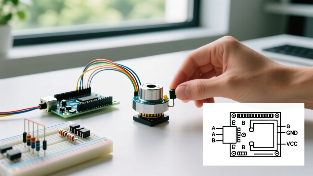
Most inexpensive GY-521 breakout boards lack adequate I2C pull-up resistors. According to the TDK InvenSense MPU-6050 specification, the I2C bus requires pull-up resistors to maintain clean logic HIGH states. Without them, the electromagnetic interference (EMI) generated by high-RPM brushless motors will corrupt the SDA and SCL lines, causing the Arduino's Wire library to hang indefinitely and crashing the flight controller mid-air.
The Fix: Solder 4.7kΩ resistors between the SDA and 3.3V lines, and the SCL and 3.3V lines directly on the breakout board. Furthermore, implement a software timeout in your code. The default Arduino Wire library can lock up the microcontroller if the I2C bus is held low by a noise spike. Use the Wire.setWireTimeout(3000, true) function to automatically reset the bus if a transaction exceeds 3 milliseconds.
Digital Low Pass Filter (DLPF) Configuration
If your drone suffers from high-frequency vibration noise feeding into your PID controller, you likely forgot to configure the IMU's internal DLPF. Writing a value of 0x03 to Register 26 (CONFIG) sets the accelerometer bandwidth to 44Hz and the gyro bandwidth to 42Hz, filtering out the 200Hz+ structural vibrations of a carbon fiber frame.
2. ESC Arming Failures and Throttle Jitter
If your motors beep continuously but refuse to spin, your Electronic Speed Controllers (ESCs) are rejecting the Arduino's arming sequence. Standard 30A Simonk or BLHeli_S ESCs expect a very specific PWM initialization sequence before they accept live throttle commands.
The Microsecond Arming Sequence
Unlike standard RC receivers, an Arduino generating PWM via the Servo library or direct timer manipulation must output a precise 1000µs (microsecond) pulse width to arm. If your code initializes with a 1500µs (mid-stick) value, the ESC will enter programming mode or refuse to arm entirely.
The Fix: Implement a strict 3-second arming routine in your setup() function:
- Send a 2000µs pulse to all ESC signal pins for exactly 2 seconds.
- Drop the pulse to 1000µs and wait for 3 seconds.
- Listen for the ESC confirmation beep (usually a rising musical tone indicating successful arming).
If you experience throttle jitter at idle (motors twitching randomly while grounded), your Arduino's 5V rail is likely suffering from voltage ripple. Ensure your ESC's BEC (Battery Eliminator Circuit) is not back-feeding the Arduino Nano's 5V pin simultaneously with the USB connection, as this causes ground loop noise that corrupts the micros() timer used for PWM generation.
3. Power Distribution and Ground Loop Interference
A quadcopter draws massive transient currents. When four 2212 920KV brushless motors spool up simultaneously, they can pull 40+ amps from a 3S LiPo battery in milliseconds. This causes severe voltage sags on the power distribution board (PDB).
Capacitor Placement and Voltage Sags
If your Arduino Nano resets mid-flight or during aggressive punch-outs, the ATmega328P's brown-out detection (BOD) is triggering due to a voltage drop below 2.7V on the 5V rail. This happens because the cheap linear voltage regulators on clone Nano boards cannot handle the transient current demands of the IMU, radio receiver, and onboard LEDs simultaneously.
The Fix: Bypass the Nano's onboard regulator entirely. Use a dedicated 5V, 3A UBEC (Universal Battery Eliminator Circuit) to power the Arduino and sensors. Solder a 1000µF low-ESR electrolytic capacitor and a 0.1µF ceramic capacitor directly across the main battery leads on the PDB to absorb high-frequency switching noise from the ESCs.
4. PID Loop Timing and Interrupt Collisions
Flight stability relies on a deterministic control loop. Your Arduino must read the IMU, calculate the PID error, and output new PWM values at a fixed frequency—typically 250Hz to 500Hz for an 8-bit microcontroller.
The delay() and millis() Trap
Many beginners use delay(4) to achieve a 250Hz loop rate. This is catastrophic for drone stability because sensor reading and I2C transmission times vary, causing loop jitter. Furthermore, if you are using software interrupts to read radio receiver PPM signals, those interrupts can pause your main loop, causing derivative (D) term spikes in your PID calculation.
The Fix: Implement a hardware timer interrupt (using a library like TimerOne) to trigger the PID calculation exactly every 4000µs. Inside the ISR (Interrupt Service Routine), simply set a boolean flag. In the main loop(), check the flag, read the sensors, and execute the math. As outlined in advanced ArduPilot PID tuning methodologies, maintaining a strict, jitter-free sample rate is mandatory to prevent the D-term from amplifying high-frequency sensor noise into violent motor oscillations.
Arduino Drone Diagnostic Matrix
| Symptom | Probable Root Cause | Hardware / Software Fix |
|---|---|---|
| IMU returns 0,0,0 or code hangs | I2C bus lockup due to EMI or missing pull-ups | Add 4.7kΩ pull-ups; enable Wire timeout |
| ESCs beep endlessly, no spin | Invalid PWM arming sequence or throttle midpoint | Code 2000µs high, then 1000µs low for 3s |
| Arduino reboots during spool-up | Voltage sag triggering Brown-Out Detection (BOD) | Install 5V 3A UBEC; add 1000µF PDB capacitor |
| Violent high-frequency oscillation | PID loop jitter or D-term amplifying I2C noise | Use hardware timer ISR; lower D-gain by 50% |
| Drone drifts continuously in one axis | IMU not calibrated level or gyro bias drift | Implement software trim; allow 5s gyro warm-up |
Final Thoughts on 8-Bit Flight Controllers
While 32-bit architectures have largely taken over the commercial FPV and autonomous drone markets, building an arduino drone remains an unparalleled educational exercise. By mastering I2C bus arbitration, hardware timer manipulation, and deterministic PID loop execution, you gain a foundational understanding of embedded control systems that applies far beyond multirotors. Keep your wiring clean, your decoupling capacitors close to the ICs, and your loop timings strict, and your custom ATmega328P drone will fly just as smoothly as the latest commercial offerings.