
The Power of Arduino Open Source Hardware
When most makers begin their electronics journey, the Arduino Uno is their gateway. But as projects evolve from breadboard prototypes to deployable IoT sensors or wearable devices, the bulky footprint and high power consumption of a standard development board become liabilities. This is where arduino open source hardware becomes your greatest asset. Because Arduino releases its schematics and PCB layouts under the Creative Commons Attribution Share-Alike (CC BY-SA 3.0) license, you can legally download, modify, and manufacture your own custom derivatives.
In this 2026 tutorial, we will walk through the exact process of taking the official Arduino Nano schematic, stripping it down for ultra-low-power battery operation in KiCad 9, and preparing it for manufacturing while strictly adhering to Open Source Hardware Association (OSHW) guidelines.
Phase 1: Sourcing the Official Design Files
Before modifying anything, you need the source files. Arduino maintains its hardware repositories on GitHub, but navigating them can be confusing due to legacy file formats.
- Navigate to the official Arduino Documentation Hub and locate the hardware section for the Nano or Uno R3.
- Download the `.brd` (board) and `.sch` (schematic) files. These are originally created in Autodesk Eagle.
- Create a dedicated project folder on your local drive named
Custom_Arduino_Node_2026and place the raw files inside.
Phase 2: Importing and Migrating to KiCad 9
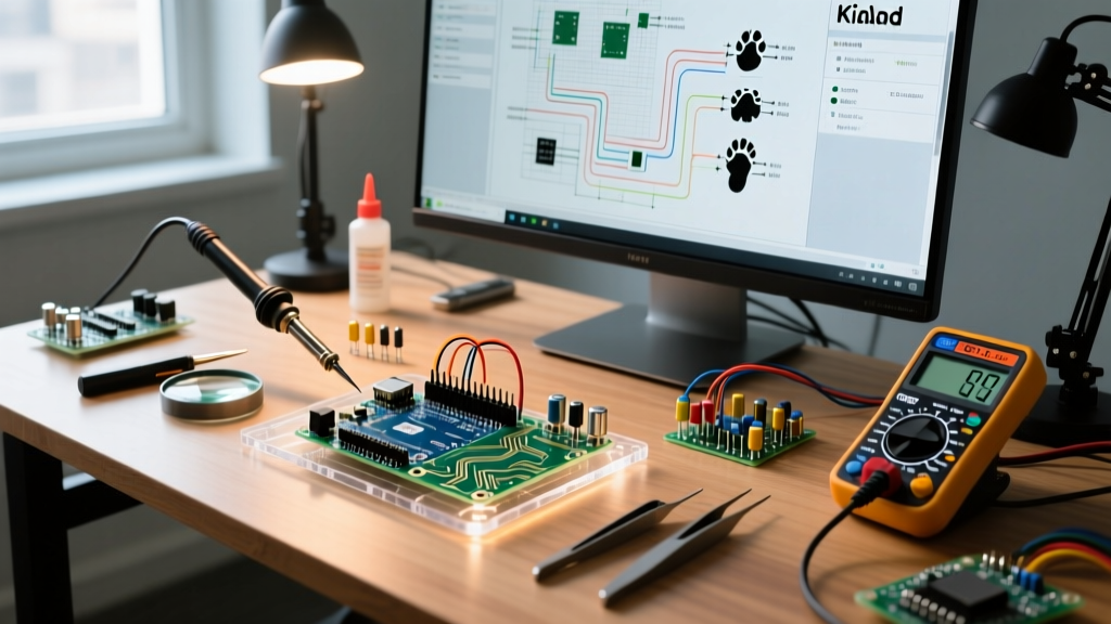
While Eagle was the industry standard a decade ago, KiCad 9 is the undisputed champion of open-source EDA tools in 2026. Migrating your Arduino open source hardware files is seamless.
- Open KiCad 9 and create a new project.
- Go to File > Import > Eagle Project.
- Select the downloaded `.brd` file. KiCad will automatically parse both the schematic and the PCB layout, mapping Eagle libraries to KiCad's internal symbol and footprint libraries.
- Run the Electrical Rules Check (ERC) on the schematic. You will likely see warnings about unconnected power flags; resolve these by adding standard KiCad `PWR_FLAG` symbols to the VCC and GND rails.
Phase 3: The 'Strip-Down' for Ultra-Low-Power
A standard Arduino Nano draws roughly 45mA to 50mA at idle, primarily due to the onboard LEDs, the USB-to-Serial bridge, and the linear voltage regulator. For a battery-powered sensor node, we need to slash this to under 0.1mA during sleep.
Step 1: Remove the USB Interface
Delete the ATmega16U2 (or CH340 on clones) and all associated USB-C circuitry, ESD protection diodes, and the 16MHz crystal tied to it. You will now program your custom board using an external USBasp or FTDI programmer via the ICSP header.
Step 2: Bypass the Linear Regulator
Remove the NCP1117 5V LDO. Linear regulators have a quiescent current draw (Iq) of 3mA to 5mA. Instead, design your board to run directly from a 3.7V LiPo cell or two AA batteries (3.0V). The ATmega328P operates natively between 2.7V and 5.5V.
Step 3: Swap the Crystal for the Internal Oscillator
Remove the 16MHz quartz crystal and its 22pF load capacitors. By utilizing the ATmega328P's internal 8MHz RC oscillator, you save board space, reduce BOM cost, and allow the microcontroller to operate safely at 3.3V.
Expert Tip: The Auto-Reset Quirk
If you plan to use an FTDI breakout for serial programming, do not forget the 0.1µF capacitor between the FTDI's DTR line and the ATmega328P's RESET pin. This is a signature piece of Arduino open source hardware design that triggers the bootloader automatically. Without it, you will have to manually press a reset button right as the compiler finishes uploading.
Phase 4: BOM Optimization and Manufacturing
When ordering from fabs like JLCPCB or PCBWay in 2026, component selection dictates your final cost. Here is a comparison between the official Nano and our stripped-down custom derivative.
| Feature | Official Arduino Nano | Custom Stripped Node (Our Design) |
|---|---|---|
| Microcontroller | ATmega328P-AU (TQFP-32) | ATmega328P-AU (LCSC: C14663) |
| Clock Source | 16MHz Quartz Crystal | Internal 8MHz RC Oscillator |
| Operating Voltage | 5V (via LDO) | 3.3V - 4.2V (Direct LiPo) |
| Idle Power Draw | ~45 mA | ~8 mA (Active) / 0.0001 mA (Sleep) |
| Approx. BOM Cost (1pc) | $24.50 (Retail) | $3.15 (JLCPCB Assembly) |
| PCB Dimensions | 45 x 18 mm | 22 x 15 mm (Custom Form Factor) |
Phase 5: OSHW Licensing and Attribution Rules
Because you are utilizing Arduino open source hardware, you are legally bound by the CC BY-SA 3.0 license. This means your derivative work must also be open-sourced under the same or a compatible license. According to the Open Source Hardware Association (OSHW), you must provide proper attribution.
- Silkscreen Attribution: Add the text 'Based on Arduino Nano, CC BY-SA 3.0' to your PCB silkscreen.
- OSHW Logo: You may use the OSHW 'gear' logo on your board, provided you have registered your project and self-certified it on the OSHW portal.
- Trademark Warning: You cannot use the word 'Arduino' in your product name, nor can you use the official Arduino infinity-loop logo. Call it the 'FluxNode-328' or similar, and state 'Arduino-compatible' in your documentation.
Phase 6: Firmware and Fuse Bit Configuration
Hardware is only half the battle. Because we removed the 16MHz crystal, a freshly flashed ATmega328P will not run your standard Arduino sketches correctly. It defaults to a 1MHz internal clock. You must reprogram the fuse bits using an ICSP programmer (like a USBasp) and `avrdude`.
Setting the 8MHz Internal Clock Fuses
Run the following command in your terminal to set the ATmega328P to use the 8MHz internal oscillator with the bootloader disabled (saving 2KB of flash space):
avrdude -c usbasp -p m328p -U lfuse:w:0xE2:m -U hfuse:w:0xD9:m -U efuse:w:0xFF:mAfter setting the fuses, you must select ATmega328P (3.3V, 8 MHz) in the Arduino IDE Boards Manager (via MiniCore) before compiling your sketches. If you skip this step, your `delay(1000)` commands will run at the wrong speed, and UART baud rates will mismatch, resulting in garbage data in your serial monitor.
Troubleshooting Common Edge Cases
When designing custom derivatives based on Arduino open source hardware, makers frequently encounter a few specific roadblocks:
- avrdude: stk500_recv(): programmer is not responding: This usually happens on custom boards if you forgot the 10kΩ pull-up resistor on the RESET pin. Without it, the reset line floats, and electrical noise will constantly reboot the MCU during programming.
- USB Enumeration Failures on Shields: If you are designing a shield rather than a standalone board, ensure your header spacing is exactly 0.6 inches (15.24mm) between the two rows. A common mistake is using standard 0.1-inch grid snapping without verifying the specific offset Arduino uses.
- Brown-Out Detection (BOD) Lockups: When running directly off a draining LiPo battery, the voltage will eventually sag below 2.7V. If the BOD fuse is disabled, the EEPROM will corrupt. Always set the BOD threshold to 2.7V (High Fuse: 0xD9) to force a safe shutdown before data corruption occurs.
Conclusion
Leveraging arduino open source hardware is the ultimate bridge between hobbyist prototyping and professional product design. By importing the official schematics into KiCad, stripping away the development-board cruft, and respecting the CC BY-SA license, you can deploy highly optimized, ultra-low-power nodes for a fraction of the retail cost. Whether you are building a fleet of agricultural soil sensors or a custom wearable, the open-source ethos ensures you never have to start your hardware design from scratch.