
The Short Answer: Is an Arduino a PLC?
If you are asking whether a standard Arduino Uno is a Programmable Logic Controller (PLC), the strict engineering answer is no. A traditional PLC is a ruggedized, deterministic computing system built to comply with the IEC 61131-3 standard, featuring galvanic isolation, 24VDC I/O, and fail-safe watchdog architectures. An Arduino, at its core, is a microcontroller development board designed for rapid prototyping.
However, if you are asking whether an Arduino can be configured to function as a PLC in an industrial environment, the answer is a resounding yes—provided you use the correct industrial-grade hardware variants and specialized runtime software. In 2026, the line between advanced Microcontroller Units (MCUs) and entry-level PLCs has blurred significantly. This configuration guide will walk you through the exact hardware architectures, software environments, and wiring practices required to successfully deploy Arduino-based systems in industrial automation.
Hardware Architecture: Why Standard Arduinos Fail in Industry
Before configuring an Arduino as a PLC, you must understand why deploying a standard $27 Arduino Uno R3 on a factory floor usually results in catastrophic failure within 48 hours.
- Voltage Mismatch: Industrial sensors (like PNP/NPN proximity switches) and actuators operate on 24VDC logic. The ATmega328P on a standard Uno operates on 5V logic. Connecting a 24V sensor output directly to a Uno digital pin will instantly destroy the microcontroller's silicon.
- Lack of Galvanic Isolation: Standard Arduinos share a common ground between the logic circuit and the I/O pins. Industrial environments are plagued by ground loops and voltage spikes. Without opto-isolators, a spike from a solenoid valve will fry the MCU.
- Electromagnetic Interference (EMI): Variable Frequency Drives (VFDs) and heavy contactors generate massive EMI. Standard Arduinos lack the shielded enclosures, filtered power supplies, and robust PCB trace routing required to prevent EMI-induced brownouts and memory corruption.
The Contenders: Industrial Arduino vs. Traditional PLC
To configure an Arduino as a PLC, you must start with industrial-grade hardware. Below is a technical comparison of standard prototyping boards, industrial Arduino variants, and legacy PLCs.
| Feature | Standard Arduino Uno R3 | Arduino Opta (AFX00003) | Siemens SIMATIC S7-1200 |
|---|---|---|---|
| Approx. Price (2026) | $27.00 | $279.00 | $450.00+ |
| Processor | ATmega328P (16 MHz) | STM32H747XI Dual-Core (480MHz/240MHz) | Proprietary Siemens SoC |
| I/O Voltage | 5VDC | 24VDC (Sink/Source) | 24VDC (Sink/Source) |
| Galvanic Isolation | None | 2kV Opto-isolation | Full Industrial Isolation |
| Programming Standard | C/C++ (Proprietary IDE) | IEC 61131-3 (Ladder, ST, FBD) | IEC 61131-3 (TIA Portal) |
| Certifications | CE, RoHS | CE, UL, IECEx, ATEX | CE, UL, IECEx, Marine |
As the table illustrates, devices like the Arduino Opta or the CONTROLLINO MAXI bridge the gap. They utilize the Arduino ecosystem but wrap the STM32 or ATmega2560 chips in 24VDC-compatible, isolated, DIN-rail-mountable enclosures.
Software Configuration: Bridging C++ and IEC 61131-3
A true PLC is defined not just by its hardware, but by its programming paradigm. Plant engineers expect to read Ladder Diagram (LD), Function Block Diagram (FBD), or Structured Text (ST). They do not want to troubleshoot C++ pointers or manage manual memory allocation on a production line.
To configure your industrial Arduino to act as a PLC, you must abandon the standard Arduino IDE and implement an IEC 61131-3 runtime. The two dominant solutions in 2026 are:
- Arduino PLC IDE: A paid, officially supported environment that compiles IEC 61131-3 languages directly to the Opta and Portenta Machine Control boards.
- OpenPLC: An open-source, free alternative that runs on almost any Arduino-compatible board (including the Mega2560 and Opta). It acts as a soft-PLC runtime.
Step-by-Step: Configuring OpenPLC on Arduino Hardware
For this guide, we will configure the open-source OpenPLC Project runtime on an Arduino-compatible industrial board. This transforms the MCU into a web-server-hosted PLC.
Phase 1: Flashing the Runtime Firmware
- Download the standard Arduino IDE and install the board definitions for your specific hardware (e.g., STM32duino for Opta, or standard AVR for Mega2560).
- Download the OpenPLC Runtime source code from the official repository.
- Open the
OpenPLC_Arduino.inosketch. In the configuration header, define your exact I/O mapping. For example, map Digital Pin 2 to%IX0.0(Input) and Digital Pin 13 to%QX0.0(Output). - Compile and flash the firmware via USB. The board is now a dedicated PLC slave.
Phase 2: Network and Logic Configuration
- Connect the Arduino to your local industrial Ethernet switch. The OpenPLC runtime will request a DHCP address (or fallback to a static IP like
192.168.1.100depending on your sketch config). - Open a web browser and navigate to the board's IP address on port 8080. You will be greeted by the OpenPLC Web Dashboard.
- Open the OpenPLC Editor on your PC. Write your automation logic using Ladder Diagram (LD). For instance, create a standard motor start/stop seal-in circuit with an emergency stop (E-Stop) normally-closed contact on
%IX0.1. - Compile the logic in the editor to generate a
.st(Structured Text) file. - Upload the
.stfile via the Web Dashboard. The MCU will halt, compile the logic into native machine code using an onboard GCC toolchain, and restart the scan cycle.
Expert Insight: When configuring the scan cycle, ensure your logic execution time remains under 5ms. While a Siemens S7-1200 guarantees deterministic scan times via a real-time operating system (RTOS), standard Arduino MCUs running OpenPLC use a cooperative multitasking loop. If you include blocking code (like long
delay()functions or heavy serial parsing), you will break the deterministic I/O scan, leading to missed sensor pulses.
Critical Edge Cases and Failure Modes
Even with industrial hardware and IEC 61131-3 software, configuring an Arduino as a PLC requires mitigating specific edge cases that traditional PLCs handle automatically.
1. Inductive Kickback and Flyback Diodes
If your Arduino Opta or Controllino is switching 24VDC relay coils or solenoids, the collapsing magnetic field generates a massive reverse voltage spike. While traditional PLCs have heavy-duty snubber circuits built into every output channel, some entry-level industrial Arduino shields rely solely on the internal body diodes of the MOSFETs. Configuration Fix: Always wire external 1N4007 flyback diodes in reverse parallel across any inductive load connected to an Arduino-based PLC output.
2. Floating Inputs and EMI Ghosting
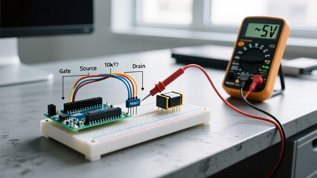
Standard microcontroller inputs have high impedance. In a factory environment, long unshielded cables running next to 480VAC VFD lines will act as antennas, inducing enough voltage to trigger a 'HIGH' state on a floating input. Configuration Fix: Enable internal pull-down resistors in your OpenPLC hardware configuration layer, or physically wire 10kΩ pull-down resistors to ground on every 24VDC sensor input line.
3. Watchdog Timer (WDT) Configuration
If a memory leak or EMI spike causes the MCU to hang, a standard Arduino will simply freeze, leaving outputs in their last known state—a massive safety hazard if a heater or press is left 'ON'. Configuration Fix: You must explicitly enable the hardware Watchdog Timer in your C++ runtime setup code. Configure the WDT to a 2-second timeout, and ensure your main PLC scan loop 'kicks' the dog. If the loop hangs, the WDT will hard-reset the MCU, forcing all I/O pins back to their safe, default HIGH-Z (off) state.
Final Verdict: When to Use Which
Is an Arduino a PLC? It is not out of the box, but it can be engineered into one. If you are building a low-cost, low-liability automation cell (e.g., a custom conveyor sorter for a small bakery, or an automated greenhouse irrigation system), configuring an Arduino Opta with OpenPLC provides 80% of the functionality of a $1,500 Allen-Bradley CompactLogix system at a fraction of the cost.
However, if your application involves safety-critical systems (e.g., robotic arm light curtains, emergency braking systems, or SIL-2/SIL-3 rated safety circuits), you must use a dedicated, certified Safety PLC. Microcontrollers, regardless of their configuration, lack the redundant voting architectures and safety certifications required for human life protection.