
The Core Challenge of Arduino Movement Tracking
Accurate Arduino movement tracking requires more than just reading raw sensor data; it demands an understanding of spatial kinematics and signal processing. When makers attempt to track 3D orientation (pitch, roll, and yaw), they typically rely on Inertial Measurement Units (IMUs). However, a fundamental physics limitation dictates that no single sensor can provide stable, long-term absolute orientation. Accelerometers are excellent for static tilt but succumb to high-frequency vibration noise. Gyroscopes provide smooth rotational velocity but suffer from integration drift over time. Magnetometers offer absolute heading relative to magnetic north but are easily corrupted by local ferrous metals and electromagnetic interference.
To achieve reliable Arduino movement tracking, engineers use sensor fusion—a mathematical technique that combines the complementary strengths of these sensors while filtering out their individual weaknesses. In 2026, the availability of advanced, low-cost IMUs and optimized microcontroller libraries has made professional-grade motion tracking accessible to hobbyists, provided the underlying hardware and algorithms are correctly configured.
Hardware Selection Matrix: Choosing the Right IMU
Selecting the correct IMU breakout board is the most critical decision in your project architecture. While legacy chips like the MPU6050 are still prevalent in budget kits, modern applications demand lower noise floors and integrated processing. Below is a comparison of the three most relevant IMU architectures for microcontroller-based tracking today.
| IMU Model | DoF | On-Board Fusion | Avg. Price (2026) | Best Application |
|---|---|---|---|---|
| TDK ICM-42688-P | 6 | No | $12 - $18 | Drones, high-speed robotics, low-noise requirements |
| CEVA BNO086 | 9 | Yes (Hardware) | $25 - $35 | VR/AR headsets, wearable motion capture, UI gestures |
| InvenSense ICM-20948 | 9 | Partial (DMP) | $15 - $22 | General robotics, GPS-denied navigation, IoT tracking |
| Legacy MPU6050 | 6 | No | $2 - $5 | Educational kits, basic tilt sensing (not recommended for precision) |
For projects requiring absolute yaw (compass heading), a 9-DoF sensor (which includes a magnetometer) is mandatory. If your Arduino movement tracking is strictly relative to a starting position (like a balancing robot), a high-performance 6-DoF sensor like the ICM-42688-P offers vastly superior gyroscope stability.
The Mathematics of Sensor Fusion
Raw data from an IMU is essentially useless for 3D tracking until it passes through a fusion algorithm. The microcontroller must calculate a Quaternion—a four-dimensional complex number representation that avoids the 'gimbal lock' singularity inherent in Euler angles (pitch/roll/yaw).
Madgwick vs. Mahony vs. Extended Kalman Filters (EKF)
- Madgwick AHRS: Developed by Sebastian Madgwick, this algorithm uses a gradient descent approach to minimize the error between the estimated gravity vector and the measured accelerometer vector. It is computationally lightweight, making it ideal for 8-bit and 32-bit Arduinos. You can explore the foundational mathematics and open-source implementations on Sebastian Madgwick's official AHRS repository.
- Mahony Filter: Similar to Madgwick but utilizes a complementary filter structure with proportional and integral (PI) control. It is slightly less aggressive in correcting accelerometer spikes, making it smoother for applications with heavy vibration.
- Extended Kalman Filter (EKF):strong> The industry standard for aerospace and autonomous vehicles. It maintains a covariance matrix to estimate sensor uncertainty dynamically. While highly accurate, it requires significant floating-point math, usually necessitating a 32-bit ARM Cortex-M4/M7 MCU (like the Arduino Portenta H7 or Teensy 4.1) rather than a standard Uno.
Pro Tip: If you are using a BNO085 or BNO086 breakout board, the sensor fusion is handled entirely in hardware by the chip's internal Cortex-M0+ processor. Your Arduino simply requests the final Quaternion via I2C or SPI, freeing up 100% of your MCU's CPU cycles for other tasks. The Adafruit BNO085 learning guide provides excellent wiring and library setup instructions for this specific hardware-fusion approach.
I2C Bus Integrity and Wiring Specifics
High-frequency movement tracking requires polling the IMU at rates between 100Hz and 500Hz. At these speeds, I2C bus capacitance and signal degradation become primary failure points. According to the official Arduino Wire library documentation, the I2C bus has strict physical limitations that makers frequently overlook.
Critical Wiring Rules for High-Speed IMUs
- Pull-Up Resistors: Most IMU breakout boards include 10kΩ pull-up resistors on the SDA and SCL lines. For 400kHz Fast Mode I2C, 10kΩ is too weak and will result in rounded signal edges and dropped packets. You must add parallel 2.2kΩ pull-up resistors to the 3.3V rail to achieve a combined resistance of roughly 1.8kΩ, ensuring sharp square waves.
- Wire Length: Keep I2C traces under 30cm (12 inches). If your IMU is mounted on a moving limb or a drone arm, use a twisted-pair cable for SDA/SCL to minimize electromagnetic crosstalk.
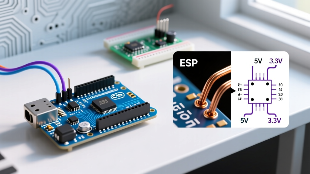
- Logic Level Shifting: Never connect a 5V Arduino (like the Uno R3 or Mega) directly to a 3.3V IMU without a bidirectional logic level converter (e.g., NXP PCA9306). Doing so will degrade the sensor's internal voltage regulator and introduce thermal noise into the gyroscope.
Real-World Failure Modes and Calibration Edge Cases
Even with perfect wiring and premium hardware, Arduino movement tracking projects often fail in the field due to environmental factors. Understanding these failure modes is what separates a novice from an expert.
Magnetic Distortion (Hard and Soft Iron)
If your 9-DoF IMU includes a magnetometer, it will be subject to localized magnetic anomalies. Hard iron distortion is caused by permanent magnets or magnetized steel near the sensor, shifting the origin of the magnetic sphere. Soft iron distortion is caused by ferromagnetic materials (like aluminum chassis or PCB ground planes) that bend the Earth's magnetic field lines, turning the perfect sphere into an ellipsoid.
Solution: You must perform a dynamic calibration routine. Upload a raw magnetometer data logging sketch, rotate the sensor in a continuous 'figure-8' pattern through all three axes for 60 seconds, and use tools like the MotionCal visualizer to generate a 3x3 correction matrix and an offset vector. Hardcode these values into your Arduino sketch.
Vibration Aliasing
When mounting an IMU on a chassis with motors (like a rover or a drone), high-frequency mechanical vibrations can alias into the accelerometer's sampling band, appearing as false DC offsets. This causes the sensor fusion algorithm to 'think' the board is tilted, resulting in severe drift.
Solution: Use mechanical isolation (sorbothane pads or O-rings) between the IMU and the chassis. Furthermore, configure the IMU's internal Digital Low-Pass Filter (DLPF). For human motion tracking, set the DLPF cutoff to 20Hz. For robotic platforms, set it between 40Hz and 100Hz, ensuring it is strictly below half of your sampling rate (Nyquist limit).
Frequently Asked Questions
Can I track absolute X, Y, Z position in a room using just an IMU?
No. IMUs measure acceleration and rotation. To get position, you must mathematically integrate acceleration twice. Because consumer-grade MEMS accelerometers have a noise floor and bias instability, the integration error compounds exponentially. Within 5 seconds, your calculated position will drift by meters. For absolute spatial tracking, you must fuse IMU data with external references like UWB (Ultra-Wideband) anchors, LiDAR odometry, or optical flow cameras.
Why does my yaw angle drift but my pitch and roll remain stable?
Pitch and roll are continuously corrected by the accelerometer, which always feels the 1G pull of gravity pointing toward the Earth's center. Yaw (rotation around the vertical Z-axis) does not change the direction of gravity. Therefore, the accelerometer cannot correct yaw. Yaw relies entirely on the gyroscope (which drifts) or the magnetometer (which is prone to noise). If your magnetometer is disabled or uncalibrated, yaw drift is physically unavoidable.