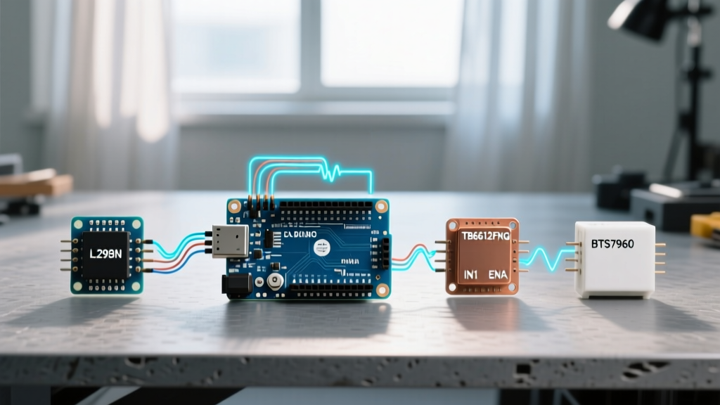

The Hidden Bottleneck: Logic Levels and Voltage Drops
Successfully pairing an arduino with motor controller hardware requires looking far beyond simple pin-to-pin wiring diagrams. The most common point of failure in DIY robotics and automation projects is not the code, but a fundamental mismatch in logic voltage levels, PWM frequency limitations, and continuous current ratings. While a microcontroller operates in the realm of milliamps and 3.3V or 5V logic, DC motors demand amps of current and generate massive inductive voltage spikes. Bridging this gap requires a deep understanding of H-bridge topologies and driver IC characteristics.
In 2026, the maker ecosystem has largely shifted toward 3.3V logic architectures (like the Arduino Nano 33 IoT and Portenta H7), yet many legacy motor drivers on the market still strictly demand 5V TTL logic to trigger their internal optocouplers. Furthermore, the physical topology of the driver—whether it uses older Bipolar Junction Transistors (BJTs) or modern Metal-Oxide-Semiconductor Field-Effect Transistors (MOSFETs)—drastically alters the voltage drop, heat dissipation, and maximum viable PWM frequency of your system.
Head-to-Head: Motor Controller Compatibility Matrix
Before wiring up your next rover or robotic arm, consult this compatibility matrix to ensure your chosen driver matches your microcontroller's logic level and your power supply's current capabilities.
| Driver IC / Module | Topology | Logic Level | Continuous Current | Max PWM Freq | Typical Price (2026) |
|---|---|---|---|---|---|
| L298N (Generic Module) | BJT H-Bridge | 5V (Strict) | 2A per channel | ~25 kHz | $4.00 - $7.00 |
| TB6612FNG (Breakout) | MOSFET H-Bridge | 2.7V - 5.5V | 1.2A (3.2A peak) | 100 kHz | $8.00 - $12.00 |
| BTS7960 (43A Module) | Infineon Half-Bridge | 5V (Opto-isolated) | 20A (43A peak) | 25 kHz | $18.00 - $24.00 |
| DRV8871 (Carrier Board) | N-Channel MOSFET | 2.2V - 5.5V | 3.6A | 50 kHz | $5.00 - $9.00 |
Optimal Pairings for Specific Arduino Boards
Let us examine three distinct, real-world pairings, analyzing why they work and the specific edge cases you must mitigate during the build process.
1. Arduino Uno R4 Minima + TB6612FNG (The Modern Standard)
The Pololu TB6612FNG Motor Driver Guide highlights the superiority of MOSFET-based drivers over legacy BJT chips. When paired with the 5V Arduino Uno R4 Minima, the TB6612FNG offers an exceptionally low on-resistance (Rds(on)) of roughly 0.5Ω. Compare this to the L298N, which suffers from a saturation voltage drop of 1.8V to 2.2V. If you are driving a 12V motor drawing 1.5A through an L298N, you lose nearly 3V to heat, delivering only 9V to the motor. The TB6612FNG drops a mere 0.75V under the same load, delivering 11.25V to the motor and running cool enough to omit a heatsink entirely.
Wiring Specifics: Connect the Arduino's 5V pin to the TB6612FNG VCC (logic power) and VM to your external motor battery (up to 15V). Ensure the STBY pin is tied HIGH to 5V, or the chip will remain in low-power sleep mode. Use 22 AWG wire for logic connections and 18 AWG for the motor outputs.
2. Arduino Mega 2560 + BTS7960 (High-Current Heavy Lifting)
For heavy-duty applications like motorized winches, large RC car conversions, or linear actuators, the BTS7960 is the undisputed king of budget high-current drivers. Capable of handling 43A peak currents, most breakout boards for the BTS7960 feature built-in optocouplers (like the PC817) to electrically isolate the high-current motor path from the delicate microcontroller logic.
The 3.3V Trap: The optocouplers on these boards typically require a forward voltage of ~1.2V and a minimum forward current of 5mA to trigger the internal LED. While a 5V Arduino Mega handles this easily via its digital pins, attempting to drive a BTS7960 directly from a 3.3V board (like an ESP32 or Arduino Nano 33 IoT) will often result in failure to trigger, or erratic PWM behavior. If you must use a 3.3V MCU with a BTS7960, you must route the logic signals through a bidirectional logic level shifter (like the Texas Instruments TXS0108E) powered by the 5V rail.
3. Arduino Nano 33 IoT + DRV8871 (Compact 3.3V Robotics)
When space and weight are at a premium, and you are operating strictly on 3.3V logic, the Texas Instruments DRV8871 is an exceptional choice. As detailed in the Texas Instruments Motor Driver Portfolio, the DRV8871 operates flawlessly with logic inputs as low as 2.2V. It requires only two PWM pins per motor (IN1 and IN2) and eliminates the need for external flyback diodes, as they are integrated into the silicon. This makes it the perfect companion for the Arduino Nano 33 IoT, allowing you to build highly compact, battery-powered robotic platforms without the bulk of level shifters or massive heatsinks.
Critical Failure Modes and Edge Cases
Even with the correct driver selected, subtle electrical gremlins can destroy your microcontroller or cause erratic behavior. Watch out for these specific failure modes:
- PWM Timer Conflicts: On AVR-based Arduinos (Uno, Mega, Nano), pins 5 and 6 share a timer with the
millis()anddelay()functions. If you use the standard Servo library alongside your motor controller, it will hijack Timer1, which can alter the PWM frequency on pins 9 and 10, causing your motors to whine or stutter. Always assign motor PWM to pins controlled by Timer2 (pins 3 and 11 on the Uno) when using servos simultaneously. - Software Serial Jitter: If your motor controller requires UART commands (like the Sabertooth series or RoboClaw) and you are using
SoftwareSerialon an Arduino Uno, the CPU interrupts required to handle the serial bits will cause massive jitter in your hardware PWM outputs. The motor will visibly twitch every time a serial byte is transmitted. The fix is to upgrade to a board with multiple hardware UARTs, like the Arduino Mega or a Teensy 4.0. - Brownout Resets: When a DC motor starts, it draws a stall current that can be 5x to 10x its running current. If your motor power supply shares a voltage regulator with your Arduino, this massive current spike will drag the voltage down, triggering the Arduino's brownout detection (BOD) and causing a random reboot. Always use completely separate power supplies for the logic and the motors, or use a high-capacity buck converter (like an LM2596) dedicated solely to the 5V logic rail.
Expert Insight: Never rely solely on the 5V output from a USB port to power your Arduino when testing high-torque motors. The back-EMF generated by a suddenly braking motor can travel backward through the ground plane and fry the USB-to-Serial IC (like the ATmega16U2) on your Arduino board. Always use an isolated USB hub during bench testing.
Advanced Wiring: Defeating Back-EMF and Ground Loops
The most frequently overlooked aspect of pairing an arduino with motor controller setups is the grounding topology. Daisy-chaining grounds (running a wire from the battery ground to the motor driver, and then from the motor driver to the Arduino) creates a ground loop. When the motor switches off, the collapsing magnetic field generates a reverse voltage spike (back-EMF). This spike travels through the shared ground wire, creating a voltage differential that the Arduino interprets as a logic HIGH on random pins, or worse, it pushes current backward through the microcontroller's ground traces, permanently damaging the silicon.
To prevent this, employ a Star Grounding Topology. Run a thick ground wire (14 AWG or 12 AWG) from the negative terminal of your high-current battery to a central terminal block or heavy copper busbar. From this single central point, run one dedicated ground wire to the motor driver's high-current GND terminal, and a separate, dedicated ground wire to the Arduino's GND pin. This ensures that high-current transients return directly to the battery without passing through the microcontroller's reference ground plane.
Furthermore, while modern drivers like the DRV8871 and TB6612FNG have internal flyback diodes, adding external Schottky diodes (like the 1N5819) across the motor terminals is a best practice for inductive loads exceeding 2A. As recommended in the Arduino Motors Electronics Guide, placing a 100nF ceramic capacitor directly across the physical motor brushes (as close to the motor casing as possible) will drastically reduce high-frequency electromagnetic interference (EMI) that can otherwise corrupt the I2C or SPI communication buses on your microcontroller.
Final Thoughts on System Integration
Choosing the right motor controller is not just about matching the amperage rating printed on the box. It requires a holistic view of your system's logic voltages, thermal constraints, and PWM timing requirements. By moving away from legacy BJT drivers like the L298N and embracing modern MOSFET architectures like the TB6612FNG or DRV8871, you will immediately notice improvements in motor torque, battery life, and overall system reliability. Always prioritize robust power delivery, implement star grounding, and respect the logic level thresholds of your chosen hardware to ensure your next robotics project operates flawlessly.