
Diagnosing Your Arduino Make Your Uno Kit Build
Soldering your own microcontroller board from scratch is a foundational rite of passage for hardware engineers and makers. The Arduino Make Your Uno kit (and similar through-hole DIY ATmega328P clone kits, typically priced between $28 and $35 as of 2026) provides an excellent platform for learning PCB assembly. However, when you plug your freshly soldered board into your PC and are met with a dead power LED or a wall of red avrdude compiler errors, the experience can be deeply frustrating.
Unlike factory-assembled boards that undergo automated optical inspection (AOI) and bed-of-nails testing, a DIY kit relies entirely on your soldering technique and component placement. This guide provides a rigorous, step-by-step error diagnosis framework to isolate and fix the most common failure modes in DIY Uno builds, utilizing multimeter testing and IDE log analysis.
Phase 1: The 'Dead Board' Power Diagnosis
If your board exhibits zero signs of life—no power LED, no USB enumeration sound from your operating system, and the IDE reports 'Board at [port] is not available'—the issue lies in the power delivery or USB data lines.
1. Voltage Regulator Orientation and Thermal Shorts
Most Make Your Uno kits utilize a linear 5V voltage regulator, such as the LM7805 or NCP1117. The LM7805 is notorious for catastrophic failure if installed backward. The correct pinout (facing the front of the board, pins pointing down) is Input, Ground, Output. If the regulator is rotated 180 degrees, applying 5V from the USB port will forward-bias internal parasitic diodes, causing the chip to overheat instantly and potentially damage the USB host port.
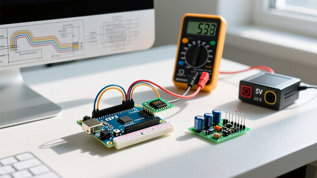
- Diagnostic Step: With the board unplugged, set your multimeter to continuity mode. Probe the USB-B connector's Pin 1 (VBUS) to the input pin of the regulator. You should read a near-zero ohm short. If you read an open circuit, check for a cold solder joint on the USB connector's power pin or a missing Schottky protection diode (often a 1N5817 or similar) if your specific kit revision includes one.
- Thermal Check: Plug the board into a low-power USB hub (to protect your main PC). Carefully touch the regulator. If it is burning hot within 3 seconds, immediately unplug it and verify the pinout and the polarity of the adjacent electrolytic capacitors (typically 10µF to 47µF).
2. USB Data Line Continuity
If the power LED illuminates but the PC does not recognize the device, the USB D+ and D- lines are compromised. According to SparkFun's multimeter diagnostic guidelines, you should use the continuity setting to trace the path from the USB connector's inner pins (Pins 2 and 3) directly to the USB-to-Serial interface chip (either an ATmega16U2 or a CH340G, depending on your kit's exact BOM).
Phase 2: Upload & Compilation Failures (The 'Timeout' Scenario)
The most common error encountered when building an Arduino Make Your Uno kit is the dreaded upload timeout. The IDE compiles the sketch successfully, but the upload fails with:
avrdude: stk500_recv(): programmer is not responding
avrdude: stk500_getsync() attempt 1 of 10: not in sync: resp=0x00
As noted in the official Arduino Troubleshooting Documentation, this error means the host PC cannot establish a serial handshake with the bootloader. On a DIY board, this is almost always a hardware-level clock or reset circuit failure.
1. The 16MHz Crystal Oscillator Circuit
The ATmega328P-PU relies on an external 16MHz HC49 crystal and two 22pF load capacitors to generate its system clock. If the crystal is not oscillating, the MCU is effectively brain-dead and cannot execute the Optiboot bootloader to receive serial data.
- The 'Tinning' Trap: Many beginners apply too much solder to the crystal pads, causing the solder to wick up the component leads and short the crystal casing to the ground plane (if the kit uses a grounded metal shell crystal).
- Capacitor Placement: The 22pF ceramic capacitors must bridge the XTAL1 (Pin 9) and XTAL2 (Pin 10) lines to ground. If you accidentally used 100nF (0.1µF) capacitors here instead of 22pF, the load capacitance will be too high, and the crystal will fail to start oscillating. Verify the capacitor color codes or measure them with an LCR meter.
2. The Auto-Reset Timing Circuit
When the Arduino IDE opens the serial port to upload code, it pulses the DTR (Data Terminal Ready) line low. This signal passes through a 100nF (0.1µF) capacitor to the ATmega328P's Reset pin (Pin 29 / PC6), momentarily pulling it low and triggering the bootloader. If this 100nF capacitor is missing, installed in the wrong location, or has a cold joint, the MCU will never reset into programming mode. The IDE will timeout after 10 attempts and throw the resp=0x00 error.
Phase 3: Component-Level Diagnostic Matrix
Use the following matrix to systematically verify the critical passive and active components on your Make Your Uno kit PCB. Ensure your multimeter is set to the correct mode before probing.
| Component | Multimeter Mode | Expected Reading / Behavior | Common Failure Symptom |
|---|---|---|---|
| 16MHz Crystal | Resistance (Ohms) | Open Loop (OL) | Shorted (solder bridge); MCU fails to boot. |
| 22pF Load Caps | Capacitance (if supported) | ~22pF | Wrong value used; Clock drift or no oscillation. |
| 10kΩ Reset Pull-up | Resistance (Ohms) | ~10,000Ω (between Reset & 5V) | Missing pull-up; MCU resets randomly from EMI noise. |
| 100nF Auto-Reset Cap | Continuity / Diode | Open Loop (OL) | Shorted; MCU held in permanent reset loop. |
| ATmega328P VCC/GND | Diode Test Mode | ~0.4V to 0.6V forward drop | 0.0V; Solder bridge on DIP socket or IC pins. |
Phase 4: Bootloader Edge Cases & ISP Flashing
A frequent point of confusion with DIY Uno kits in 2026 is the state of the ATmega328P-PU chip included in the bag. While some premium kits ship with a pre-flashed Optiboot bootloader, many budget-oriented 'Make Your Uno' kits include a blank, factory-fresh ATmega328P. A blank chip does not know how to listen to the USB-Serial adapter; it only listens to the ICSP (In-Circuit Serial Programming) SPI pins.
How to Flash the Bootloader via ISP
If you have verified the crystal, reset circuit, and USB-Serial chip, but still cannot upload, your main MCU likely lacks a bootloader. You will need an external ISP programmer (like a $12 USBasp) or a second, working Arduino configured as an 'Arduino as ISP'.
- Connect the ISP programmer to the 2x3 ICSP header on your DIY board. Ensure Pin 1 (MISO) aligns with the dot indicator on the PCB silkscreen.
- Open Arduino IDE 2.3.x. Navigate to Tools > Programmer and select your ISP device (e.g., 'USBasp' or 'Arduino as ISP').
- Select Tools > Burn Bootloader. The IDE will use
avrdudeto set the correct fuse bits (specifically setting the BOOTRST fuse and configuring the 16MHz external crystal) and write the Optiboot hex file to the uppermost 512 bytes of the flash memory. - Once the IDE reports 'Done burning bootloader', disconnect the ISP, plug in the USB cable, and attempt a standard sketch upload.
Phase 5: Visual Inspection & Flux Residue Diagnostics
Do not underestimate the impact of chemical residue on high-impedance analog and digital traces. If you used cheap, non-rosin flux paste during assembly, the leftover residue can become slightly conductive in humid environments. This can cause 'ghost' readings on the analog pins or interfere with the high-speed I2C/SPI buses.
- Cleaning Protocol: Use 99% Isopropyl Alcohol (IPA) and a stiff-bristled ESD-safe brush to scrub the solder joints, particularly around the dense DIP-28 socket and the ATmega16U2/CH340G chip. Allow the board to dry completely for 15 minutes before reapplying power.
- Magnification: Use a 10x loupe or a digital USB microscope to inspect the space between the ATmega328P pins. A microscopic solder sphere bridging Pin 1 (Reset) and Pin 2 (RX) will permanently hold the board in reset or corrupt incoming serial data.
Frequently Asked Questions (FAQ)
Why does my DIY Uno get hot near the voltage regulator when uploading?
The LM7805 regulator dissipates excess voltage as heat. If you are powering the board via the DC barrel jack (if your kit includes one) with a 9V or 12V wall adapter, the regulator must drop 4V to 7V. At just 100mA of current draw, this generates significant heat. For USB-only operation (5V input), the regulator is essentially bypassed or operating at a very low dropout, and should remain cool. If it gets hot on USB power, you have a short circuit on the 5V rail.
Can I use the Make Your Uno kit without the USB-to-Serial chip?
Yes. If your kit includes an ATmega16U2 but you prefer to use an external FTDI cable or a 3.3V ESP32 for serial bridging, you can simply omit the USB-Serial IC and its associated crystal/capacitors during assembly. You will need to wire the TX/RX lines and the DTR auto-reset capacitor directly to the main ATmega328P pins and your external serial adapter.
What causes the 'Not in sync: resp=0x1e' error specifically on DIY kits?
The resp=0x1e or resp=0x00 errors indicate that avrdude is receiving garbage data or no data at all. On DIY kits, this is frequently caused by swapping the RX and TX traces. The silkscreen on some clone boards labels RX and TX from the perspective of the USB chip, while the IDE expects the labels from the perspective of the main ATmega328P. If uploads fail, try physically swapping the wires between the USB-Serial chip and the main MCU's RX (Pin 2) and TX (Pin 3) pins using jumper wires to test the theory before desoldering.
Conclusion
Building an Arduino Make Your Uno kit is an exercise in patience and precision. When errors occur, resist the urge to immediately desolder components. By following a structured diagnostic matrix—verifying power delivery, isolating the 16MHz clock circuit, confirming the auto-reset capacitor, and ensuring the Optiboot bootloader is present—you can systematically eliminate variables. Keep your multimeter handy, trust the datasheet pinouts over ambiguous silkscreen labels, and you will have a fully functional, self-built microcontroller platform ready for your next embedded project.