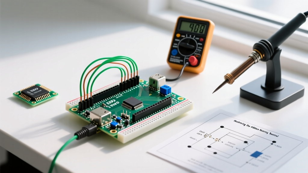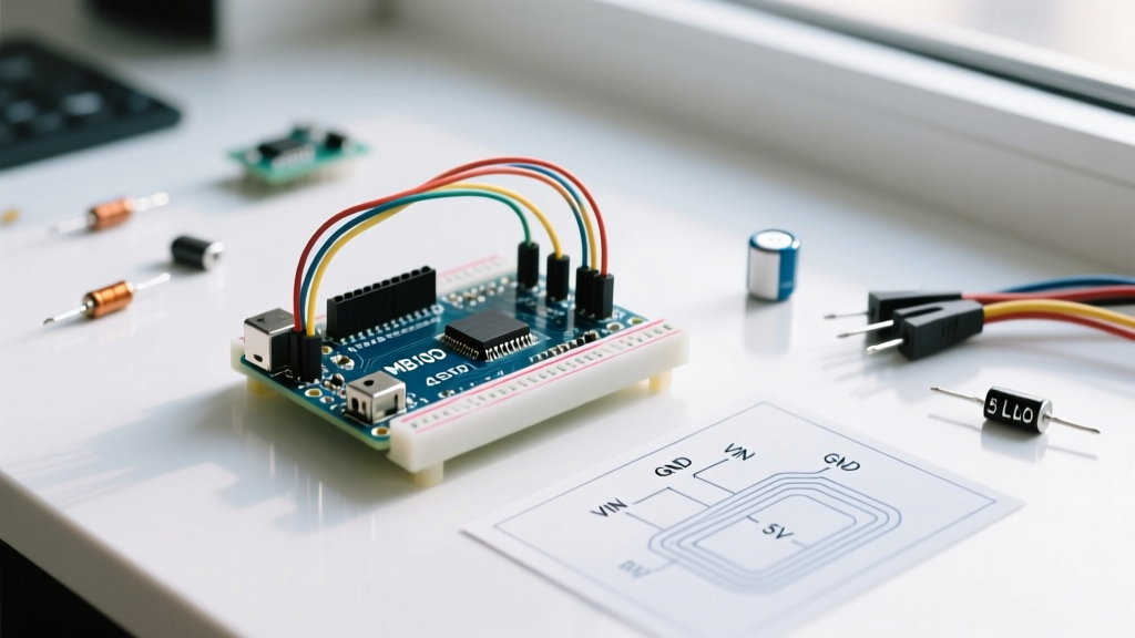

Quick Reference: The Standard Arduino Power Supply Module
When hobbyists and engineers search for an arduino power supply module, the MB102 breadboard PSU is almost universally the first hardware they encounter. Designed to snap directly into standard solderless breadboards, this module provides dual-rail voltage options (3.3V and 5V) from a single DC barrel jack or micro-USB input. While it remains a staple in prototyping kits, its underlying Linear Dropout (LDO) regulator topology imposes strict thermal and current limitations that are rarely documented in basic tutorials.
At the heart of the MB102 are two AMS1117 voltage regulators—one configured for 3.3V and one for 5.0V. Understanding the silicon-level behavior of these regulators is critical to preventing thermal shutdowns, melted breadboard contacts, and damaged microcontrollers.
Core FAQ: Voltage, Current, and Jumper Settings
What is the actual maximum current output?
The AMS1117 datasheet advertises a maximum output current of 800mA. However, in the context of the MB102 module, continuous safe current is limited to roughly 300mA–400mA. The module lacks active cooling and relies on minimal PCB copper pours for heatsinking. Pushing 800mA through the 3.3V regulator with a 9V input will trigger the chip's internal thermal shutdown within seconds.
How do the voltage selection jumpers work?
The module features two 3-pin headers with jumper caps that route power to the breadboard rails. The configuration matrix is as follows:
- Both jumpers on 5V pins: Both rails output 5V.
- Both jumpers on 3.3V pins: Both rails output 3.3V.
- Mixed configuration (one on 5V, one on 3.3V): The left breadboard rail receives 5V, while the right rail receives 3.3V. This is ideal for mixed-logic circuits featuring 5V relays and 3.3V ESP32 modules.
Can I power a servo motor directly from the 5V rail?
No. A standard SG90 micro servo draws roughly 200mA at idle but can spike to 700mA+ during stall conditions. Larger servos like the MG996R can pull 2.5A. The MB102's LDO will instantly overheat and drop voltage, causing your Arduino to brownout and reset. Always use a dedicated buck converter or separate battery eliminator circuit (BEC) for inductive loads.
The Thermal Trap: LDO Power Dissipation Math
The most common failure mode of the arduino power supply module is thermal throttling. Because the MB102 uses linear regulators, it dissipates excess voltage as heat. According to Texas Instruments' LDO design guidelines, you must calculate power dissipation ($P_D$) before selecting your input voltage.
Formula: $P_D = (V_{IN} - V_{OUT}) \times I_{LOAD}$
Example: Input = 12V, Output = 3.3V, Load = 400mA (0.4A)
$P_D = (12 - 3.3) \times 0.4 = 3.48 \text{ Watts}$
The SOT-223 package used on the MB102 has a junction-to-ambient thermal resistance ($\theta_{JA}$) of approximately 50°C/W on standard 1oz copper without forced air. A 3.48W dissipation yields a temperature rise of 174°C above ambient. This will violently exceed the AMS1117’s 165°C thermal shutdown threshold, and may physically melt the plastic of your breadboard.
Expert Rule of Thumb: If you need 3.3V, never exceed a 6.5V input on the barrel jack. If you need 5V, keep the input under 7.5V. For higher input voltages, you must switch to a switching buck converter.
Module Comparison: LDO vs. Switching Regulators
As maker projects grow in complexity, the limitations of linear modules become apparent. Here is how the standard MB102 compares to modern alternatives available in 2026.
| Feature | MB102 (Standard LDO) | LM2596 Buck Converter | USB-C PD Decoy (e.g., ZY12PDN) |
|---|---|---|---|
| Topology | Linear (LDO) | Switching (Buck) | USB-C PD Negotiation |
| Max Safe Current | ~400mA (Thermal limited) | 2.0A - 3.0A | 3.0A+ (Depends on GaN charger) |
| Efficiency | 30% - 60% (High heat) | 85% - 92% (Low heat) | 95%+ (Direct PD delivery) |
| Input Voltage | 6.5V - 12V DC / 5V USB | 4.5V - 40V DC | 20V USB-C PD Source |
| Best Use Case | Low-power logic, basic sensors | Motors, LEDs, high-current arrays | Modern bench prototyping, IoT |
Troubleshooting Common Clone Board Failures
The market is flooded with sub-$2 clone versions of the MB102. While the schematic is identical to the original, cost-cutting in manufacturing leads to specific failure modes that Arduino power documentation frequently warns against.
- Missing Reverse Polarity Protection: Genuine modules include a Schottky diode (often a 1N5819) after the barrel jack. Many clones omit this to save $0.02 per unit. If you accidentally use a center-negative power adapter, you will instantly destroy the AMS1117 chips and potentially backfeed 12V into your microcontroller's 5V rail, killing the MCU.
- Micro-USB Port Bypass: On the MB102, the micro-USB port does not route through the 5V regulator. It connects directly to the 5V rail. If your jumper is set to 3.3V and you plug in USB, you are feeding 5V directly into the 3.3V breadboard rail, bypassing the regulator entirely and risking your 3.3V components.
- Undersized Barrel Jacks: Clone DC jacks often use inferior internal leaf springs. At currents above 500mA, the contact resistance increases, causing the jack itself to become a localized heater, melting the surrounding plastic housing before the LDO even registers the load.
The 2026 Perspective: Upgrading to USB-C Power Delivery
While the MB102 remains a legacy staple, the maker community in 2026 has largely pivoted toward USB-C Power Delivery (PD) decoy boards for breadboard power. Modules utilizing the CH224K or ZY12PDN ICs allow you to plug in a standard 65W GaN laptop charger and negotiate fixed voltages (5V, 9V, 12V, 15V, or 20V) directly.
By using a USB-C PD breakout board with standard 2.54mm header pins, you eliminate the thermal waste of LDOs entirely. As highlighted in SparkFun's comprehensive guide to voltage regulation, switching topologies and direct digital negotiation are vastly superior for mixed-voltage environments. A PD decoy module costs roughly $3.50, slightly more than an MB102, but provides up to 3A of 5V power with near-zero heat generation.
Step-by-Step: Safely Integrating the MB102
If you are using the MB102 for a low-power prototyping session, follow these steps to ensure stable logic levels:
- Step 1: Set the jumpers to your desired voltage before applying power.
- Step 2: Use a regulated 7V to 9V DC wall adapter (center-positive). Avoid unregulated transformers, which can output 14V+ under no-load conditions and fry the LDO.
- Step 3: Add a 100µF electrolytic capacitor and a 0.1µF ceramic decoupling capacitor across the 5V and GND rails on your breadboard, as close to your microcontroller's VIN pin as possible. The MB102's onboard capacitors are often low-quality and insufficient for high-speed digital switching noise.
- Step 4: Monitor the AMS1117 chip temperature with your finger after 5 minutes of operation. If it is too hot to keep your finger on it (>60°C), you must reduce the input voltage or lower your current draw.
Final Verdict
The MB102 arduino power supply module is an acceptable tool for blinking LEDs, testing basic I2C sensors, and learning circuit topology. However, it is fundamentally a thermal bottleneck. For any project involving Wi-Fi transmission (like the ESP8266/ESP32, which draw 300mA+ spikes), motor control, or addressable LED strips, abandon the LDO breadboard module in favor of a dedicated buck converter or a modern USB-C PD negotiation board.