
Understanding the Magnetometer for Arduino
When building autonomous navigation robots, digital compasses, or non-contact current sensors, selecting the right magnetometer for Arduino is a foundational decision. Unlike simple Hall effect sensors that merely detect the presence of a magnetic threshold, modern MEMS (Micro-Electromechanical Systems) magnetometers measure the precise vector strength and direction of magnetic fields across three axes (X, Y, and Z). This capability allows microcontrollers to calculate exact heading angles relative to Earth's magnetic north, making them indispensable for maker projects requiring spatial awareness.
However, integrating these sensors goes far beyond plugging in four wires. Magnetic fields are notoriously susceptible to environmental interference, and the maker market is flooded with legacy modules that can cause severe debugging headaches. This guide breaks down the physics, hardware selection, wiring protocols, and real-world failure modes you need to know to successfully deploy a magnetometer in your next Arduino project.
The Physics: How MEMS Magnetometers Measure Fields
To troubleshoot sensor noise, you must first understand how the silicon inside the chip actually detects magnetism. Modern breakouts rely on one of three primary magnetoresistive effects:
- AMR (Anisotropic Magnetoresistance): Used in older but reliable chips. The electrical resistance of a permalloy strip changes depending on the angle of the applied magnetic field. AMR sensors are highly sensitive but can be permanently 'magnetized' or damaged if exposed to strong neodymium magnets.
- GMR (Giant Magnetoresistance): Utilizes alternating nanoscale layers of ferromagnetic and non-magnetic metals. GMR offers a larger signal-to-noise ratio than AMR and is highly resistant to external magnetic shocks.
- TMR (Tunnel Magnetoresistance): The current gold standard for high-precision consumer electronics. TMR sensors use a quantum tunneling effect across an ultra-thin insulating barrier, providing exceptional thermal stability and micro-tesla level resolution.
To put sensor sensitivity into perspective, we must look at the environment we are measuring. According to the NOAA National Centers for Environmental Information, Earth's magnetic field ranges from approximately 25 to 65 microteslas (0.25 to 0.65 Gauss) depending on your geographic location. Therefore, a magnetometer for Arduino must be able to resolve changes in the single-digit microtesla range to provide a smooth, jitter-free compass heading.
Choosing the Right Module: 2026 Hardware Comparison
The maker market has shifted significantly over the last few years. The once-ubiquitous HMC5883L is now effectively obsolete, yet counterfeit or rebranded chips are still sold under its name. Here is a comparison of the most reliable I2C magnetometer modules available for Arduino today.
| Sensor IC | I2C Address | Resolution | Approx. Price | Best Use Case |
|---|---|---|---|---|
| QMC5883L | 0x0D | 15-bit | $2.00 - $4.00 | Budget projects, basic compass robots |
| LIS3MDL | 0x1C / 0x1E | 16-bit | $9.00 - $12.00 | High-precision drones, wearable IMUs |
| BMM150 | 0x10 - 0x13 | 16-bit | $5.00 - $8.00 | 9-DOF sensor fusion, Bosch ecosystems |
| HMC5883L | 0x1E | 12-bit | N/A (Legacy) | Avoid (High counterfeit rate) |
The HMC5883L Trap: If you buy a cheap "HMC5883L" breakout board from a third-party marketplace today, it is almost certainly a QMC5883L chip with a different silkscreen. If your Arduino code hangs or returns zeros, check your I2C scanner. If the address resolves to0x0Dinstead of0x1E, you have a QMC chip and must use a QMC-specific library.
Deep Dive: The LIS3MDL Advantage
For professional-grade maker projects, the STMicroelectronics LIS3MDL is the premier choice. As detailed in Adafruit's comprehensive LIS3MDL guide, this chip features a selectable full-scale range of ±4, ±8, ±12, or ±16 Gauss. This dynamic range adjustment is critical: use ±4 Gauss for high-resolution Earth compass readings, but switch to ±16 Gauss if your Arduino is tracking a strong neodymium magnet on a linear actuator to prevent sensor saturation.
Wiring and I2C Configuration
Almost all modern magnetometers communicate via the I2C bus. The Arduino Wire library handles the low-level protocol, but physical wiring requires attention to detail.
Standard I2C Pinout
- VCC: Connect to 3.3V or 5V (most modern breakouts have an onboard LDO regulator, but verify your specific board's silkscreen).
- GND: Connect to Arduino GND. Keep this wire as short as possible to prevent ground loops.
- SCL: Connect to Arduino A5 (on Uno/Nano) or the dedicated SCL pin near the AREF pin.
- SDA: Connect to Arduino A4 (on Uno/Nano) or the dedicated SDA pin.
The Pull-Up Resistor Edge Case
I2C is an open-drain protocol, meaning it requires pull-up resistors to pull the SDA and SCL lines HIGH. While the Arduino's internal pull-ups (typically 20kΩ to 50kΩ) can sometimes work, they are often too weak for reliable communication at 400kHz (Fast Mode). Many budget QMC5883L clone boards omit the standard 4.7kΩ surface-mount pull-up resistors to save fractions of a cent. If your sensor randomly drops packets, add external 4.7kΩ resistors between the SDA/SCL lines and VCC, or force the Arduino to use standard 100kHz mode by adding Wire.setClock(100000); in your setup() function.
Real-World Failure Modes and Interference
The most common reason a magnetometer for Arduino fails in the field is not bad code, but environmental magnetic distortion. Magnetometers cannot distinguish between Earth's magnetic field and local interference. Here are the primary culprits you must design around:
1. The Solderless Breadboard Trap
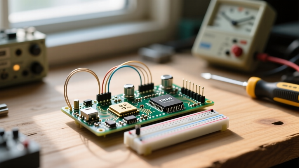
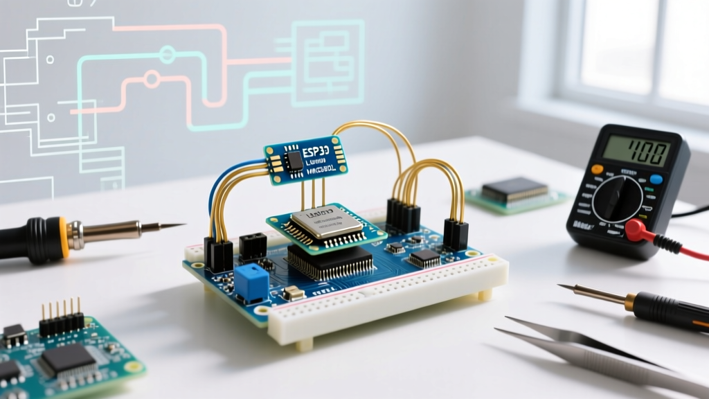
Standard solderless breadboards are constructed with hundreds of tiny spring-steel contacts, and many feature a solid steel backing plate. Steel is ferromagnetic; it bends and concentrates local magnetic flux lines. If you mount your magnetometer directly on a breadboard, your X and Y axis readings will be severely skewed, and rotating the board will yield non-linear, jagged compass headings. Solution: Mount the sensor on a protoboard or use jumper wires to elevate it at least 3 inches above the breadboard.
2. USB Cable and Power Rail Noise
Current flowing through a wire generates a circular magnetic field (Ampere's Law). The 5V power rail and ground traces on your Arduino PCB, as well as the copper inside your USB cable, carry fluctuating current depending on what else is powered (like servos or LEDs). This creates a dynamic 'hard iron' offset, particularly on the Z-axis. Keep your magnetometer physically isolated from high-current motor driver shields and thick power cables.
3. Soft Iron vs. Hard Iron Distortion
When calibrating your sensor, you must account for two types of physical interference:
- Hard Iron: Caused by permanent magnets or magnetized steel (like nearby screws or a speaker). This adds a constant offset vector to your readings, shifting the center of your X/Y data plot away from (0,0).
- Soft Iron: Caused by non-magnetized ferromagnetic materials (like aluminum enclosures or copper planes) that bend the Earth's magnetic field. This stretches your X/Y data plot from a perfect circle into an ellipse.
To fix this, you must perform a calibration routine where you rotate the Arduino in a full 3D sphere, record the min/max values for all three axes, and apply an offset matrix in your code to re-center the data into a perfect sphere.
Summary for Makers
Successfully deploying a magnetometer for Arduino requires moving beyond basic library examples. By selecting a modern sensor like the LIS3MDL or QMC5883L, ensuring robust I2C pull-up resistances, and physically isolating the chip from ferromagnetic breadboards and high-current traces, you will achieve stable, degree-accurate heading data. Always run an I2C address scan before writing your code to verify you aren't falling victim to legacy chip rebranding, and implement a basic min/max calibration routine to guarantee your digital compass points true north.