
The Enduring 'Hello World' of Hardware: Why the Button-LED Circuit Still Matters
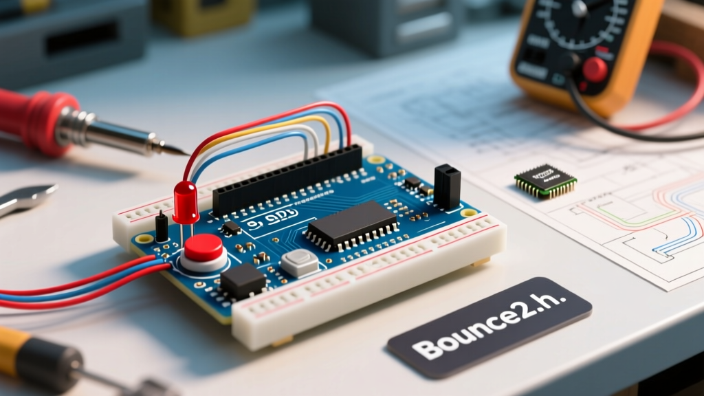
Every maker's journey begins with a single, illuminating moment: pressing a tactile switch and watching an LED ignite. While the arduino led with button project is universally recognized as the foundational 'Hello World' of physical computing, treating it as a trivial exercise is a mistake that haunts engineers later in complex projects. In 2026, as embedded systems integrate into higher-noise environments and IoT edge devices demand ultra-reliable user inputs, mastering the nuances of switch debouncing, pull-up configurations, and contact oxidation is more critical than ever.
This community resource roundup curates the most robust wiring paradigms, battle-tested code libraries, and specific hardware recommendations favored by professional embedded developers and advanced hobbyists. Whether you are prototyping on a solderless breadboard or designing a custom PCB for a commercial enclosure, these insights will elevate your digital I/O implementations from fragile experiments to production-grade interfaces.
Wiring Paradigms: Pull-Up vs. Pull-Down Configurations
The most common point of failure in basic microcontroller circuits is a floating pin. When a pushbutton is open (not pressed), the input pin is disconnected from both VCC and GND, acting as an antenna that picks up ambient electromagnetic interference (EMI). To solve this, the community universally relies on pull resistors. However, choosing between an external pull-down and the microcontroller's internal pull-up drastically alters your circuit's noise immunity and logic flow.
Comparing the Configurations
| Feature | External Pull-Down (10kΩ to GND) | Internal Pull-Up (INPUT_PULLUP) |
|---|---|---|
| Logic State (Unpressed) | LOW (0V) | HIGH (VCC) |
| Logic State (Pressed) | HIGH (5V/3.3V) | LOW (0V) |
| Resistor Value | Typically 10kΩ (External) | 20kΩ - 50kΩ (Internal ATmega328P) |
| Wiring Complexity | Higher (Requires extra components) | Lowest (Direct pin-to-switch-to-GND) |
| Noise Immunity | High (Lower impedance path to GND) | Moderate (Higher impedance susceptible to EMI) |
For standard breadboard prototyping, the INPUT_PULLUP method is the undisputed champion of convenience. It eliminates the need for external resistors and reduces wiring clutter. However, if your arduino led with button setup involves wire runs longer than 30 centimeters, the higher impedance of the internal pull-up (up to 50kΩ on the ATmega328P) can lead to phantom triggers. In these scenarios, the community strongly recommends an external 4.7kΩ or 10kΩ pull-down resistor to create a stiffer, more noise-resistant voltage divider.
Top Community Code Libraries for Button Management
Raw digitalRead() polling inside a loop() is insufficient for real-world applications due to mechanical switch bounce—a phenomenon where the metal contacts physically chatter for 1 to 5 milliseconds before settling. While basic delay(50) hacks work for simple LED toggles, they block the main thread, ruining the timing of LEDs, sensors, and communications.
The Gold Standard: Bounce2
The Bounce2 library by Thomas Ouellet Fredericks remains the most heavily utilized debouncing library in the Arduino ecosystem. Unlike older libraries that rely on blocking delays, Bounce2 uses a non-blocking state machine based on millis().
- Key Feature: The
fell()androse()methods allow you to trigger an LED toggle exactly once per press, ignoring the continuousLOWstate while the button is held. - Implementation Tip: Set your debounce interval to 10ms using
button.interval(10);. This safely covers 99% of standard tactile switches without introducing perceptible input lag. - Memory Footprint: Highly optimized, consuming minimal SRAM, making it ideal for constrained chips like the ATtiny85.
Alternative: EasyButton for Complex State Machines
If your project requires distinguishing between a short press, a long press, and a double-click to cycle through different LED patterns (e.g., breathing, strobe, solid), the community frequently points to the EasyButton library. It abstracts the timing logic, allowing you to attach callback functions directly to specific press events, keeping your main loop remarkably clean.
Hardware Selection: Tactile Switches vs. Panel Mount Pushbuttons
The physical component you choose dictates the tactile feedback, lifespan, and environmental resilience of your project. Sourcing cheap, unbranded switches from bulk marketplaces often leads to contact oxidation and premature failure.
For PCB Prototyping: C&K PTS645 Series
The C&K PTS645 series (e.g., PTS645SM43SMTR92 LFS) is the industry-standard surface-mount and through-hole tactile switch. Priced at roughly $0.12 to $0.25 per unit in low volumes, they offer a crisp actuation force (typically 160gf or 260gf) and a rated lifespan of 100,000 cycles. Their sealed construction provides basic dust resistance, crucial for preventing the 'stuck button' failure mode common in open-air maker projects.
For Enclosure Integration: E-Switch PV4 Series
When moving from a breadboard to a 3D-printed or aluminum enclosure, panel mount pushbuttons are required. The E-Switch PV4F240SS-341 (approx. $4.50 - $6.00) is a community favorite. It features IP67 water and dust resistance, a stainless steel actuator, and integrated LED illumination rings. Wiring these requires careful attention to the LED forward voltage (usually 2.1V for red, 3.2V for blue/green) to calculate the correct current-limiting resistor (typically 150Ω for a 5V logic supply).
Advanced Edge Cases: Debounce Failures and EMI in Long Wire Runs
Even with the Bounce2 library and high-quality switches, advanced makers frequently encounter 'phantom presses' when the arduino led with button circuit is scaled up. This is almost always caused by Electromagnetic Interference (EMI) or capacitive coupling.
Expert Troubleshooting Rule: If your button triggers when you walk past it or when a nearby relay switches, your wiring is acting as an antenna. Software debouncing cannot fix hardware EMI.
The Hardware Fix: RC Low-Pass Filters
To eliminate EMI-induced phantom presses on wire runs exceeding 1 meter, the community standard is to add a hardware debounce circuit. Place a 100nF (0.1µF) MLCC ceramic capacitor in parallel with the switch (between the input pin and GND). This creates an RC low-pass filter that physically absorbs high-frequency noise spikes before the microcontroller's Schmitt trigger input can register them as a logic state change. For extremely noisy industrial environments, pairing this with a 74HC14 hex Schmitt-trigger inverter IC guarantees flawless signal conditioning.
Curated Community Tutorials and Schematics
To deepen your understanding of digital I/O and switch mechanics, we recommend bookmarking the following authoritative resources:
- SparkFun Switch Basics Tutorial: An excellent visual breakdown of SPST, SPDT, and DPDT switch topologies, complete with oscilloscope readings showing actual mechanical bounce waveforms. Read it on SparkFun's Learn Portal.
- Arduino Official Digital Pins Documentation: Crucial for understanding the exact current sourcing/sinking limits of the ATmega328P and SAMD21 architectures, ensuring you don't accidentally fry your GPIO by wiring an LED without a current-limiting resistor. Available at the Arduino Docs Center.
Frequently Asked Questions (FAQ)
Why does my LED flicker when I press the button?
Flickering during the press or release phase is the visual manifestation of mechanical switch bounce. The microcontroller is reading the rapid 1-to-0-to-1 transitions and executing your LED toggle code multiple times in a few milliseconds. Implementing a non-blocking software debounce library like Bounce2, or adding a 100nF capacitor across the switch terminals, will eliminate this flicker entirely.
Can I wire multiple buttons to a single analog pin?
Yes, using a resistor ladder network (voltage divider). By wiring buttons in series with different resistor values (e.g., 1kΩ, 2.2kΩ, 4.7kΩ) to a single analog input, you can read distinct voltage drops using analogRead(). This is a common space-saving technique in 2026 for custom macro-keypads, though it requires careful calibration in code to account for resistor tolerance (typically ±5%).
Do I need a resistor for the LED if I'm using a button?
The button's state does not negate the need for an LED current-limiting resistor. An ATmega328P GPIO pin can safely source or sink a maximum of 20mA (absolute max 40mA). A standard 5mm red LED has a forward voltage of ~2.0V. On a 5V Arduino, you must use at least a 150Ω resistor (calculated via Ohm's Law: R = (5V - 2V) / 0.02A = 150Ω) to prevent destroying the microcontroller's internal output transistor.