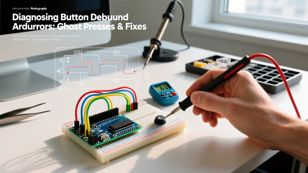

The Physics of Contact Chatter: Why Ghost Presses Happen
When designing interactive microcontroller projects, encountering a single physical button press that registers as three or four digital inputs is a universal rite of passage. This phenomenon, known as contact bounce, is not a software bug; it is a fundamental reality of electromechanical physics. When you actuate a mechanical switch—such as the ubiquitous 6x6mm tactile switch or an Omron B3F series momentary pushbutton—the internal metal contacts do not mate perfectly on the first collision. Instead, they physically rebound, separate, and collide again multiple times before settling into a stable closed state.
If you were to probe a bouncing switch with an oscilloscope, you would not see a clean, instantaneous transition from HIGH to LOW. Instead, you would observe a chaotic, high-frequency square wave lasting anywhere from 1 millisecond to over 50 milliseconds, depending on the switch's metallurgy, spring tension, and actuation force. To an ATmega328P or ESP32 microcontroller executing millions of instructions per second, this 5ms chatter looks exactly like a user rapidly mashing the button dozens of times. Diagnosing and resolving these button debounce Arduino errors requires a systematic approach that addresses both the electrical signal path and the firmware logic.
Diagnosing the 3 Most Common Debounce Errors
Before applying a fix, you must accurately diagnose how the bounce is manifesting in your specific circuit. Misdiagnosing the symptom often leads to over-engineered solutions that introduce new latency issues.
Error 1: The Multiple-Count Increment
Symptom: A menu counter increments by 3 or 4 instead of 1 per press, or a toggle LED changes state multiple times unpredictably.
Root Cause: The firmware is polling the pin state in the loop() without tracking the previous state, or it is triggering on the raw LOW state rather than the transition edge (the exact moment the signal changes from HIGH to LOW). Because the main loop runs in microseconds, it reads the 'LOW' state multiple times during the bounce window.
Error 2: The Interrupt Storm (MCU Lockup)
Symptom: The microcontroller freezes, the hardware watchdog timer (WDT) triggers a reset, or I2C peripherals (like OLED displays) stop responding immediately after a button press.
Root Cause: You have attached a hardware interrupt using attachInterrupt() on the CHANGE or FALLING edge. A single noisy press fires the Interrupt Service Routine (ISR) 20 times in 5 milliseconds. If your ISR contains blocking code, heavy computation, or I2C transactions, the interrupt vector table becomes congested, starving the main loop and crashing the I2C bus state machine. As noted in the official Arduino interrupt documentation, ISRs must be kept as short as possible, but bounce inherently violates this by spamming the vector.
Error 3: State Machine Desynchronization
Symptom: A long-press vs. short-press detection algorithm fails, or a multi-button chord (pressing two buttons simultaneously) registers incorrectly.
Root Cause: The bounce on one switch delays the firmware's ability to poll the second switch, or the timing thresholds for 'long press' are corrupted by the microsecond-level jitter introduced during the initial contact closure.
Hardware Diagnosis: Fixing Bounce at the Circuit Level
The most robust way to handle button debounce Arduino errors is to prevent the noisy signal from ever reaching the microcontroller's GPIO pin. Hardware debouncing offloads the CPU and guarantees clean logic levels.
The RC Filter + Schmitt Trigger Approach
A simple Resistor-Capacitor (RC) low-pass filter can smooth out the high-frequency bounce. By placing a 10kΩ resistor in series with the switch and a 100nF capacitor to ground, you create a time constant (τ = R × C) of 1 millisecond. This charges the capacitor slowly, masking the microsecond bounces.
The Hidden Trap: An RC filter outputs an exponential voltage curve, not a sharp digital edge. As the voltage slowly crosses the ATmega328P's logic threshold (typically ~2.5V for a 5V system), the internal digital input buffer can oscillate, causing the exact same ghost presses you were trying to fix. To solve this, you must route the RC signal through a Schmitt trigger IC, such as the 74HC14 hex inverter. The 74HC14 features built-in hysteresis, meaning it has separate upper and lower voltage thresholds, ensuring a single, razor-sharp digital transition regardless of the input curve's slope.
Software Diagnosis: Moving Beyond the delay() Trap
When hardware modifications are impossible due to PCB constraints or BOM cost limits, firmware must handle the chatter. However, the implementation dictates system stability.
The Cardinal Sin: Using delay()
Beginners often attempt to fix bounce by inserting delay(50); immediately after reading a button press. While this technically ignores the 50ms bounce window, it halts the entire microcontroller. In a 2026 embedded ecosystem where MCUs are expected to handle PID loops, wireless telemetry, and LED multiplexing concurrently, a 50ms blocking delay is unacceptable and will cause severe system jitter.
The Professional Standard: Millis-Based State Tracking
The correct software approach tracks the exact timestamp of the last valid state change using the millis() function. The highly respected Ganssle Group's Guide to Debouncing outlines that a robust software debouncer must record the time of the initial edge, ignore all subsequent reads until the debounce interval (usually 20ms) has elapsed, and then verify the pin state is still stable. Libraries like Bounce2 (by Thomas Ouellet Fredericks) encapsulate this logic, providing non-blocking .fell() and .rose() methods that integrate seamlessly into complex state machines without stalling the CPU.
Comparison Matrix: Hardware vs. Software Debouncing
| Method | CPU Overhead | BOM Cost Impact | Latency Added | Best Application Scenario |
|---|---|---|---|---|
| RC Filter + 74HC14 | Zero | +$0.15 per switch | ~2ms | High-EMI environments, critical safety interlocks |
| Software Polling (Bounce2) | Low (Microseconds) | $0.00 | 20ms - 50ms | Standard UI buttons, menu navigation, consumer IoT |
| Interrupt + Software Timer | Medium (Context Switching) | $0.00 | 5ms - 20ms | Battery-powered deep-sleep wake-up circuits |
| Blocking delay() | 100% (Halts CPU) | $0.00 | 50ms+ | None (Deprecated practice) |
Advanced Edge Cases: EMI, Long Wires, and Pull-Up Weakness
Sometimes, what appears to be mechanical contact bounce is actually electromagnetic interference (EMI) masquerading as a switch closure. This is a frequent diagnosis error in industrial or automotive Arduino deployments.
The Weak Pull-Up Vulnerability
The ATmega328P features internal pull-up resistors that are typically between 20kΩ and 50kΩ. While convenient, these high-impedance paths are highly susceptible to capacitive coupling from nearby AC mains, relays, or PWM-driven motor controllers. A voltage spike induced on the GPIO trace can pull the pin below the logic LOW threshold for a few microseconds, triggering an interrupt.
The Fix: Disable the internal pull-up and use an external 1kΩ to 4.7kΩ pull-up resistor. This lower impedance creates a 'stiffer' logic HIGH that requires significantly more induced current to pull the voltage down, effectively immunizing the pin against ambient EMI. For runs longer than 30cm, always use shielded twisted-pair cable, grounding the shield at the MCU end only to prevent ground loops.
Diagnostic Pro-Tip: If your ghost presses only occur when a nearby relay clicks or a motor spins, you are not dealing with mechanical switch bounce. You are dealing with EMI. No amount of software debouncing will reliably fix an EMI-induced interrupt storm; you must harden the physical circuit with lower impedance pull-ups and proper bypass capacitors (100nF across the switch terminals).
Summary of Diagnostic Workflow
To permanently resolve button debounce Arduino errors, follow this triage sequence:
- Verify the Signal: Hook an oscilloscope or logic analyzer to the GPIO pin. If the bounce lasts >10ms, your switch is mechanically degraded or of poor quality (replace with Omron or C&K equivalents).
- Check the Environment: If the 'bounce' occurs without physically touching the button, diagnose for EMI and lower your pull-up resistor values.
- Audit the Firmware: Strip all
delay()calls from your button logic. Implement edge-detection state tracking viamillis()or the Bounce2 library. - Protect your ISRs: Never perform I2C or SPI transactions inside a button interrupt. Use the ISR only to set a
volatile booleanflag, and handle the heavy lifting in the mainloop().
By understanding the physical realities of electromechanical contacts and the architectural limits of microcontroller interrupts, you can build interfaces that are responsive, deterministic, and entirely immune to ghost presses. For further reading on signal integrity in embedded systems, All About Circuits provides an excellent primer on switch physics that complements these diagnostic strategies.