
The 2026 Standard for Addressable LED Workflows
Building an Arduino LED light strip project often devolves into a frustrating mess of spaghetti code, mysterious data-line flickering, and severe voltage drops. In 2026, with the mass adoption of high-density COB LED strips and advanced 3.3V microcontrollers like the Arduino Nano ESP32, the bottleneck is rarely hardware capability. Instead, the primary point of failure is a disorganized developer workflow. Professional lighting engineers and seasoned makers do not guess wire gauges or write custom delay loops from scratch. They rely on a systematic, modular pipeline.
This guide outlines a streamlined, professional workflow for designing, wiring, and coding addressable LED strips. By implementing strict power architecture rules, mandatory logic level shifting, and a WLED-to-FastLED prototyping pipeline, you will eliminate 90% of common hardware bugs before you even write your first line of C++.
Phase 1: Hardware Selection and Power Architecture
The most critical workflow optimization happens before you open the Arduino IDE: selecting the correct LED protocol and designing a robust power injection topology. In 2026, standard 5V SMD 5050 strips (like the legacy WS2812B) are being rapidly replaced by 12V architectures and dot-free COB (Chip-on-Board) strips for professional installations.
Strip Protocol Comparison Matrix
| LED IC / Strip Type | Operating Voltage | Max Current per LED | Key Advantage | Best Use Case |
|---|---|---|---|---|
| WS2812B (Standard SMD) | 5V DC | 60mA (RGB) | Ubiquitous, cheap ($12/5m) | Short runs, wearables, breadboard prototyping |
| WS2815 (12V SMD) | 12V DC | 15mA (RGB) | Backup data line, lower current | Long architectural runs (up to 10m without injection) |
| SK6812 RGBW | 5V DC | 80mA (RGBW) | Dedicated warm/cool white channel | Cabinet lighting, bias lighting requiring pure white |
| WS2812-COB (Dot-Free) | 5V / 12V | Varies (High Thermal) | Continuous neon-like beam, no hotspots | Visible accent lighting, aluminum channel builds |
The Power Injection Rule of Thumb
Never rely on the Arduino’s 5V pin or a single USB connection to power more than 15 to 20 LEDs. A standard 5-meter roll of 60 LEDs/m WS2812B strip contains 300 LEDs. At maximum white brightness (60mA per LED), this strip demands 18 Amps of continuous current.
Optimized Workflow Step: Always spec your power supply at 120% of the calculated maximum draw to prevent thermal throttling and capacitor whine. For an 18A 5V strip, purchase a 20A to 25A power supply. The Mean Well LRS-300-5 (5V, 40A, typically priced around $45-$55 in 2026) is the industry gold standard for enclosed LED projects. Inject power at both ends of a 5-meter strip, and every 2 meters for high-density COB strips to prevent voltage sag, which manifests as red-shifted colors at the end of the strip.
Phase 2: Signal Integrity and the Level Shifter Mandate
The most common reason makers abandon an Arduino LED light strip project is unexplainable flickering, random color flashing, or the first LED behaving erratically. This is almost always a logic-level mismatch.
Modern microcontrollers, including the Arduino Nano ESP32, Raspberry Pi Pico, and standard ESP32 dev boards, operate at 3.3V logic. However, the WS2812B and SK6812 datasheets specify that a valid HIGH signal on the DIN pin must be at least 0.7 × VCC. If VCC is 5V, the data signal must be at least 3.5V. Feeding a 3.3V signal into a 5V strip places the logic threshold in an undefined gray zone, resulting in data corruption that worsens with wire length and electromagnetic interference.
The 74AHCT125 Solution
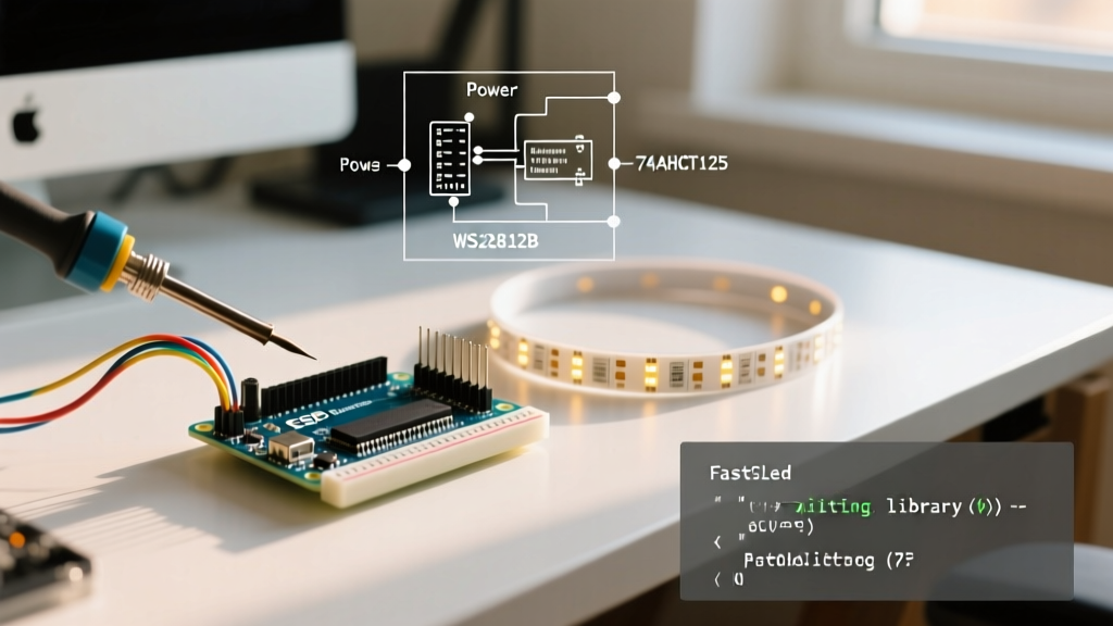
Do not use resistor voltage dividers or simple transistor logic for high-speed LED data lines; they ruin the precise nanosecond timing required by the WS281x protocol. Instead, integrate a Texas Instruments SN74AHCT125 quad bus buffer IC (costing roughly $1.50 for a DIP package) into your workflow.
Workflow Hack: Keep a dedicated 'Level Shifter Breakout Board' in your toolkit. Wire the 74AHCT125 VCC to 5V, GND to GND, and route your 3.3V Arduino data pin into the 1A input. The 1Y output will safely provide a crisp, 5V logic signal capable of driving long data lines without timing degradation.
Additionally, always place a 330Ω to 470Ω resistor on the data line between the level shifter output and the LED strip’s DIN pad. This prevents high-frequency ringing and protects the first LED’s internal logic gate from voltage spikes during hot-plugging.
Phase 3: The WLED-to-FastLED Prototyping Pipeline
Writing custom C++ animation loops from scratch for every new physical layout is a massive waste of development time. Professional lighting designers use a two-stage software workflow to separate visual design from embedded deployment.
Stage 1: Visual Prototyping with WLED
Before finalizing your Arduino code, flash an ESP32 development board with WLED. WLED is an open-source firmware that provides a web-based UI for mapping LED layouts, testing color palettes, and verifying power limits. Use WLED to:
- Map complex physical layouts (serpentine routing, 2D matrices, or 3D rings).
- Test the visual appeal of transitions and palettes without recompiling code.
- Verify that your power supply handles the specific animation’s average power draw (since full-white is rarely used in actual animations).
Stage 2: Embedded Deployment with FastLED
Once the visual design and hardware layout are locked, port the logic to the FastLED official documentation library for your final Arduino deployment. FastLED offers unparalleled control over color math, dithering, and hardware-specific timing.
When porting, utilize FastLED’s built-in timing macros to maintain a non-blocking architecture. Never use the delay() function in a production LED sketch, as it halts the microcontroller, preventing you from reading button inputs, processing MQTT smart-home commands, or updating secondary sensors.
// Optimized Non-Blocking FastLED Architecture
#include <FastLED.h>
#define NUM_LEDS 300
#define DATA_PIN 5
CRGB leds[NUM_LEDS];

void setup() {
  FastLED.addLeds<WS2812B, DATA_PIN, GRB>(leds, NUM_LEDS);
  FastLED.setBrightness(128);
}

void loop() {
  EVERY_N_MILLISECONDS(20) {
    // Update animation state (e.g., moving a sine wave)
    for(int i = 0; i < NUM_LEDS; i++) {
      leds[i] = CHSV((millis() / 10) + (i * 2), 255, 255);
    }
  }

  EVERY_N_MILLISECONDS(50) {
    // Handle secondary tasks like reading sensors or Wi-Fi
    checkSensorInputs();
  }

  FastLED.show();
}
Phase 4: Modular Wiring and Field Replaceability
Soldering data and power wires directly to an Arduino Nano or custom PCB creates a permanent, fragile bond that is a nightmare to troubleshoot if a wire breaks inside a wall or enclosure. Optimize your physical assembly workflow by standardizing on JST-SM 3-pin connectors for data lines and Molex Mini-Fit Jr. or heavy-duty screw terminals for power injection.
By using standardized connectors, you can swap out a faulty microcontroller or replace a damaged LED segment in under 60 seconds without needing a soldering iron on-site. For 2026 builds utilizing high-current 12V COB strips, ensure your power connectors are rated for at least 10A per pin to prevent plastic melting and fire hazards.
Troubleshooting Matrix: Common Failure Modes
When your optimized workflow encounters an edge case, use this diagnostic matrix to identify the root cause instantly without resorting to trial-and-error.
| Symptom | Root Cause | Optimized Fix |
|---|---|---|
| First LED works, rest are chaotic/flickering | Missing or blown data-line resistor; signal degradation. | Add 470Ω resistor on DIN. Ensure data wire is < 50cm or use a twisted pair with GND. |
| Colors shift to red/orange at the end of the strip | Severe voltage drop (VCC falling below 4.5V at the far end). | Inject 5V power at both the start and end of the strip. Upgrade wire gauge to 18 AWG or thicker. |
| Entire strip flickers randomly at high brightness | Power supply overcurrent protection tripping or logic noise. | Verify PSU rating. Add a 1000µF electrolytic capacitor across the VCC/GND terminals at the strip start. |
| LEDs display correct colors but animation is stuttering | Blocking code (delay()) or Wi-Fi interrupts on ESP32. |
Refactor code using EVERY_N_MILLISECONDS. Move Wi-Fi tasks to Core 0 and FastLED to Core 1. |
Conclusion
Treating your Arduino LED light strip project as a structured engineering workflow rather than a casual hobby experiment drastically reduces build time and hardware failures. By standardizing on 12V architectures for long runs, mandating 74AHCT125 level shifters for 3.3V microcontrollers, and separating visual design (WLED) from embedded logic (FastLED), you ensure your installations are robust, scalable, and ready for 2026’s demanding smart-home and artistic environments.