
The "Laser Arduino" Ecosystem: Emission vs. Sensing
When makers search for a laser Arduino setup, they are typically tackling one of two entirely different hardware paradigms: laser emission (using diodes for engraving, cutting, or optical tripwires) or laser sensing (using VCSEL Time-of-Flight modules for precision distance measurement). Both require specific wiring topologies, logic-level considerations, and safety protocols. This quick-reference FAQ addresses the most common hardware bottlenecks, failure modes, and integration techniques for both paradigms in 2026.
FAQ Part 1: Laser Diode Emission Modules
Q: Can I wire a KY-008 red laser directly to an Arduino digital pin?
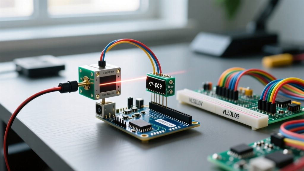
The KY-008 is a ubiquitous 650nm, 5V red dot laser module costing roughly $1.50. While many basic tutorials show it wired directly to an Arduino Uno digital pin (with the 'S' pin to D13, middle to 5V, and '-' to GND), this is a bad engineering practice. According to the official Arduino digital pin specifications, the ATmega328P absolute maximum DC current per I/O pin is 40mA, with a recommended operating limit of 20mA. The KY-008 can draw 25mA to 35mA depending on the batch and the value of its onboard current-limiting resistor (which varies wildly among cheap clones).
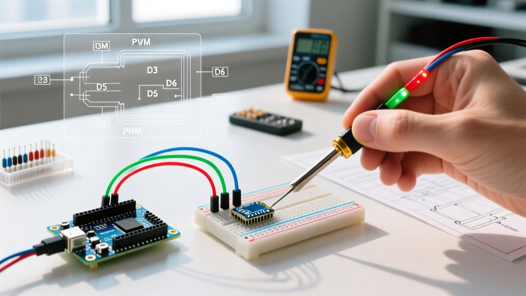
The Expert Fix: Drive the KY-008 using a standard 2N2222 NPN bipolar junction transistor (BJT). Connect the Arduino digital pin to the BJT base via a 220Ω resistor, the emitter to GND, and the laser module's ground leg to the collector. This limits the Arduino pin current to roughly 15mA while safely switching the laser's full load.
Q: How do I drive a 5W+ blue engraving laser with an Arduino?
High-power blue diode lasers (like the 445nm Endurance 40W Pro or generic 5W/10W optical output modules) require 12V to 24V and draw anywhere from 2A to 5A. Never connect these to an Arduino board's voltage regulator.
- Power Supply: Use a dedicated 12V/5A or 24V/5A switching power supply.
- Switching Component: You must use a Logic-Level N-Channel MOSFET. The IRLB8721 is ideal because its RDS(on) is fully specified at Vgs = 4.5V (matching the Arduino's 5V logic). The older IRLZ44N works but operates less efficiently at 5V gate drive.
- PWM Frequency: Arduino's default `analogWrite()` PWM frequency is ~490Hz. For laser engraving grayscale (dithering), this causes visible banding. Use a library like
TimerOneto push Pin 9 or 10 to 20kHz to 25kHz. This ensures the laser diode switches fast enough to create smooth material burns without audible high-pitch whining.
FAQ Part 2: Laser Time-of-Flight (ToF) Sensors
Q: Why does my VL53L0X return an 8190mm error or fail I2C?
The VL53L0X (940nm VCSEL) is the industry standard for short-range laser distance sensing ($4 for clones, ~$12 for Adafruit/Pololu breakouts). The "8190mm" or "8191mm" readout is not a real distance; it is the STMicroelectronics API's default overflow/error code indicating the sensor cannot resolve the phase shift of the returning photons.
Common Causes & Fixes:
- Out of Range / Low Reflectivity: The VL53L0X maxes out at ~2 meters, but only on highly reflective white targets. On dark or angled surfaces, range drops to 600mm. Increase the
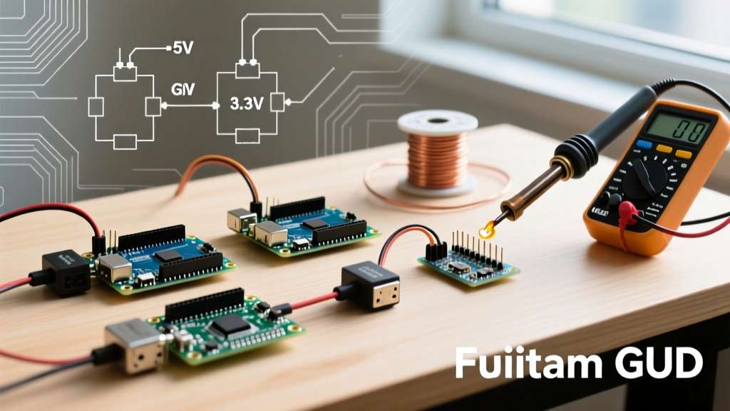
timing_budgetin your code from the default 33ms to 200ms to allow more photon accumulation. - I2C Logic Level Mismatch: The raw VL53L0X chip operates at 2.8V. If you are using a bare Pololu board with a 5V Arduino, you are risking I2C bus lockups or silicon damage. Use a bi-directional logic level shifter (like the BSS138) or buy a breakout board with onboard 3.3V regulation and level shifting.
- Missing Pull-ups: Ensure 4.7kΩ pull-up resistors are present on the SDA and SCL lines. Many cheap clone boards omit these, leading to intermittent I2C timeouts.
Sensor Technology Comparison Matrix
Choosing the right distance sensor is critical. Here is how laser ToF compares to traditional alternatives for Arduino projects:
| Feature | Laser ToF (VL53L1X) | Ultrasonic (HC-SR04) | Sharp IR (GP2Y0A21) |
|---|---|---|---|
| Technology | 940nm VCSEL Laser | 40kHz Sound Waves | Infrared Triangulation |
| Max Range | 4000mm (4 meters) | 4000mm | 800mm |
| Accuracy | ± 1mm to ± 5mm | ± 3mm to ± 10mm | Highly non-linear |
| Blind Spot | None (0mm min) | ~20mm to 50mm | ~100mm |
| Interference | Sunlight (IR noise) | Soft/Angled surfaces | Ambient IR, dark objects |
| Avg Cost (2026) | $6.00 - $15.00 | $1.50 - $3.00 | $8.00 - $12.00 |
Safety & Compliance Quick Reference
⚠️ CRITICAL SAFETY WARNING: Never look directly into a laser beam or its specular reflections. For high-power blue diode lasers (>500mW optical output), always wear wavelength-specific OD5+ safety goggles (e.g., 400nm-450nm protection). Ensure your workspace is enclosed to prevent stray beam hazards.
When integrating lasers into commercial or public-facing Arduino projects, you must adhere to the FDA CDRH laser product regulations and the ANSI Z136.1 standard. Below is a quick reference for laser classifications commonly encountered in maker spaces:
- Class 1: Safe under all conditions (e.g., VL53L0X VCSEL sensors, enclosed laser printers).
- Class 2: Visible lasers < 1mW. Safe due to the human blink reflex (e.g., standard laser pointers).
- Class 3R: Visible lasers 1mW - 5mW. Low risk, but direct viewing should be avoided (e.g., KY-008 modules).
- Class 3B: 5mW - 500mW. Hazardous. Direct eye exposure causes immediate damage. Requires key switches and emission indicators on Arduino enclosures.
- Class 4: > 500mW. Extreme Hazard. Can cause eye/skin damage and start fires. Includes almost all DIY laser engravers and cutters. Requires full interlock systems.
Hardware Troubleshooting Matrix
| Symptom | Probable Cause | Actionable Fix |
|---|---|---|
| Laser diode flickers during PWM fading | PWM frequency too low or MOSFET gate capacitance too high for Arduino pin | Add a 10kΩ pull-down resistor on MOSFET Gate-to-Source; increase PWM freq via Timer1. |
VL53L0X hangs on init() |
I2C address collision or missing XSHUT pin management | Pull XSHUT pin HIGH to enable. Ensure no other device uses 0x29. |
| Engraving is charred/black instead of clean | Speed too slow or lack of air assist | Increase G-code feed rate by 20%; add a 12V PC fan air-assist nozzle to clear smoke. |
| Arduino resets when laser turns on | Voltage sag on 5V rail due to shared ground/power loops | Isolate laser PSU from Arduino PSU; tie grounds together at a single star point. |
For further reading on advanced ToF calibration, refer to the Adafruit VL53L0X comprehensive guide, which details how to adjust the signal rate limit and sigma thresholds for highly accurate Arduino robotics applications.