
Understanding the AD5171: Beyond Standard Digital Potentiometers
When designing precision analog circuits, mechanical potentiometers introduce noise, drift, and physical wear. While standard digital potentiometers solve the mechanical issues, they often lose their wiper position when power is cycled. Enter the Analog Devices AD5171, a 64-position, I2C-compatible digital potentiometer that solves the volatility problem through a unique CMOS fuse technology. For makers and engineers working on an ad5171 arduino project, understanding how this chip bridges the gap between digital control and permanent analog calibration is critical.
Retailing at approximately $1.85 to $2.40 per unit on major distributors like Mouser and DigiKey in 2026, the AD5171 is an affordable solution for one-time calibration tasks, sensor trimming, and programmable gain amplifiers. However, its One-Time Programmable (OTP) nature and strict analog signal boundaries mean it cannot be treated exactly like a standard microcontroller peripheral.
The OTP (One-Time Programmable) Advantage
Most digital potentiometers use SRAM or EEPROM to store wiper settings. SRAM is volatile (loses data on power loss), while EEPROM is non-volatile but has a limited write cycle lifespan (typically 100,000 to 1,000,000 cycles). The AD5171 utilizes an electrical fuse mechanism. During your manufacturing or calibration phase, you use your Arduino to find the perfect resistance value, then send a specific I2C command to 'blow' the CMOS fuse. This permanently locks the wiper to that exact position on every subsequent power-up. It is the digital equivalent of applying Loctite to a mechanical trimmer screw.
Hardware Specifications and Package Variants
The AD5171 is available in several resistance values and package types. Choosing the right variant is essential for your PCB layout and signal requirements.
| Part Number Suffix | Resistance | Package | Terminals | Typical Use Case |
|---|---|---|---|---|
| AD5171BRJ5 | 5 kΩ | SOT-23-6 | Rheostat (A, W) | Current limiting, LED dimming |
| AD5171BRJ10 | 10 kΩ | SOT-23-6 | Rheostat (A, W) | Op-amp feedback loops |
| AD5171BRJ50 | 50 kΩ | SOT-23-6 | Rheostat (A, W) | Voltage dividers, bias networks |
| AD5171BRM10 | 10 kΩ | MSOP-8 | Potentiometer (A, W, B) | Full 3-terminal voltage division |
Note: The SOT-23-6 packages are internally configured as rheostats (variable resistors) where the 'B' terminal is either tied internally or omitted, saving board space. If your circuit requires a true 3-terminal voltage divider, you must source the MSOP-8 package.
Wiring the AD5171 to an Arduino via I2C
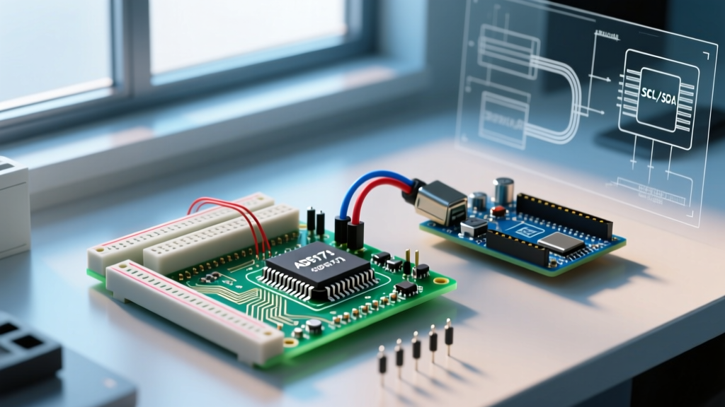
The AD5171 communicates via a standard I2C bus, but it lacks configurable address pins. Its I2C address is hardcoded at the factory (typically 0x2C or 44 in decimal for the standard BRJ variants). This means you can only place one AD5171 on a single I2C bus without using an I2C multiplexer like the TCA9548A.
Essential Pin Connections (SOT-23-6)
- VDD (Pin 2): Connect to Arduino 5V or 3.3V (ensure it matches your I2C logic levels).
- GND (Pin 3): Connect to common ground.
- SCL (Pin 4): Connect to Arduino SCL (A5 on Uno/Nano).
- SDA (Pin 1): Connect to Arduino SDA (A4 on Uno/Nano).
- A (Pin 6) & W (Pin 5): Your analog signal input and wiper output.
CRITICAL DESIGN RULE: Analog Signal Boundaries
The most common failure mode when integrating an ad5171 arduino circuit is exceeding the analog pin voltage limits. The analog signals present at pins A and W must never exceed VDD or drop below GND. If VDD is 5V, and you attempt to pass a 12V audio or sensor signal through the digipot, the internal ESD protection diodes will conduct, permanently destroying the silicon. Always buffer external signals or ensure they are strictly bounded within the VDD rails.
Arduino Code Implementation
Because the AD5171 uses a simplified I2C protocol, you do not need a heavy third-party library. The chip expects a single data byte containing the 6-bit wiper position (0-63) padded with two control bits. We can use the native Arduino Wire Library to handle the transmission.
#include <Wire.h>

// AD5171 typical I2C address (verify with an I2C scanner if unsure)
const int AD5171_ADDRESS = 0x2C;

void setup() {
  Wire.begin();
  Serial.begin(9600);

  // Set wiper to mid-scale (position 32 out of 63)
  setWiperPosition(32);
  Serial.println("Wiper set to mid-scale.");
}

void loop() {
  // Sweep the wiper up and down
  for (int i = 0; i <= 63; i++) {
    setWiperPosition(i);
    delay(50);
  }
  for (int i = 63; i >= 0; i--) {
    setWiperPosition(i);
    delay(50);
  }
}

void setWiperPosition(byte position) {
  // Constrain to 6-bit value (0-63)
  position = position & 0x3F;

  Wire.beginTransmission(AD5171_ADDRESS);
  // The AD5171 expects the data byte directly after the address
  Wire.write(position);
  Wire.endTransmission();
}
Executing the OTP Fuse Sequence
If your project requires permanent calibration, you must blow the OTP fuse. According to the Analog Devices AD5171 Datasheet, this is not a standard I2C write. It requires a specific high-voltage sequence or precise timing command depending on the exact silicon revision, but generally follows these rules:
- VDD Requirement: VDD must be stable between 4.5V and 5.5V. Do not attempt to blow the fuse at 3.3V.
- Set the Wiper: Write your desired final resistance value to the wiper using standard I2C.
- Send OTP Command: Transmit the specific OTP program command byte (typically
0x80combined with the wiper data, but consult your specific revision's datasheet table for the exact OTP register map). - Timing: The fuse blowing process takes approximately 400ms. Do not interrupt power during this window.
Warning: OTP programming is irreversible. Always test your circuit using standard volatile writes before executing the fuse command.
Common Failure Modes and Troubleshooting
When your ad5171 arduino setup fails to respond or behaves erratically, check these specific edge cases:
- Missing I2C Pull-Up Resistors: The AD5171 features open-drain I2C outputs. If your Arduino board does not have onboard pull-ups (many barebones ATmega328P boards lack them), you must add 4.7 kΩ pull-up resistors from SDA and SCL to VDD. The NXP I2C Specification (UM10204) details how bus capacitance affects pull-up values; for high-speed or long-wire runs, 2.2 kΩ may be required.
- Wiper Resistance (Rw): The wiper itself has an internal resistance (typically 60Ω to 100Ω). If you set the digipot to position 0, you will not measure 0Ω; you will measure the wiper resistance. Account for this in precision current-sensing circuits.
- Address Conflicts: Because the address is hardcoded, if you are using multiple sensors on the same bus, ensure no other device shares the
0x2Caddress. Use an I2C scanner sketch to map your bus before finalizing the firmware.
AD5171 vs. Alternatives: Which Digipot Should You Choose?
Is the AD5171 the right choice for your specific microcontroller project? Compare it against standard alternatives to make an informed component selection.
| Feature | AD5171 (Analog Devices) | MCP4131 (Microchip) | Mechanical Trimmer (Bourns) |
|---|---|---|---|
| Interface | I2C | SPI | Physical Screw |
| Positions | 64 (6-bit) | 129 (7-bit) | Infinite (Analog) |
| Memory Type | OTP Fuse (Permanent) | Volatile (SRAM) | N/A (Physical) |
| Write Cycles | 1 (OTP), Unlimited Volatile | Unlimited Volatile | ~200 Cycles (Wear) |
| Best Application | Factory Calibration, Sensor Trimming | Dynamic Audio Volume, Active Filters | Prototyping, Manual Tuning |
Final Thoughts on Integration
Integrating the AD5171 into an Arduino ecosystem provides a robust, professional-grade method for locking in analog calibrations without relying on external EEPROM or battery-backed SRAM. By respecting the strict analog voltage boundaries, properly configuring your I2C pull-ups, and understanding the irreversible nature of the CMOS fuse, you can elevate your DIY electronics and commercial prototypes from hobbyist experiments to production-ready designs.