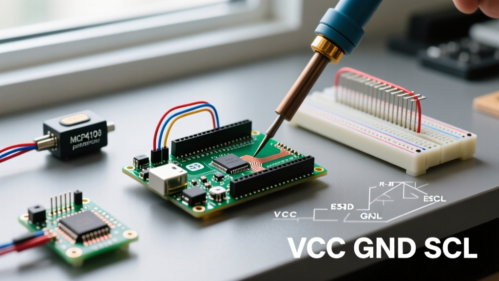

Decoding the 'Arduino Digital Resistor' Misconception
When makers, students, and embedded engineers search for an Arduino digital resistor, they are typically colliding with a fundamental terminology gap. Microcontrollers like the ATmega328P (Arduino Uno) or the Espressif ESP32 do not possess native, dynamically adjustable resistors built into their standard General Purpose Input/Output (GPIO) pins. A silicon GPIO pin can only act as a high-impedance input, a pull-up/pull-down input, or a push-pull output.
Instead, this search intent generally maps to one of three distinct electronic concepts required in microcontroller design:
- Digital Potentiometers (Digipots): Dedicated ICs that act as programmable resistors controlled via SPI or I2C.
- R-2R Resistor Ladders: Networks of fixed resistors attached to multiple digital pins to synthesize an analog voltage (DAC).
- GPIO Biasing and Protection: The external and internal resistors required to safely interface digital pins with the physical world.
This quick-reference guide and technical FAQ breaks down exactly what you need for your 2026 embedded projects, complete with specific IC model numbers, wiring topologies, tolerance requirements, and hard electrical limits.
1. Digital Potentiometers: The True 'Programmable Resistor'
If your project requires a resistor whose value changes via Arduino code, you need a digital potentiometer. Unlike mechanical pots, digipots use an internal ladder of resistors and CMOS switches to select a specific wiper position. They are essential for programmable gain amplifiers, digital audio volume control, and automated calibration circuits.
Top Digipot ICs for Arduino Projects (2026 Market)
Selecting the right digipot depends on your required interface, resolution, and memory type. Volatile digipots reset to a default value on power loss, while non-volatile models retain their wiper position.
| IC Model | Interface | Resolution | Resistance | Memory | Est. Price (1pc) |
|---|---|---|---|---|---|
| Microchip MCP41010 | SPI | 256 Steps | 10 kΩ | Volatile | $1.45 |
| Analog Devices AD5272 | I2C | 1024 Steps | 100 kΩ | Non-Volatile (OTP) | $2.85 |
| Microchip MCP4551 | I2C | 257 Steps | 100 kΩ | Volatile | $1.60 |
Expert Warning: Wiper Current Limits
A common failure mode in beginner circuits is attempting to drive high-current loads (like motors or high-power LEDs) directly through a digipot wiper. The wiper terminal on ICs like the MCP41010 is typically limited to 1mA to 5mA. Exceeding this will permanently destroy the internal CMOS switches. Always use the digipot to set a reference voltage or control the base/gate of a transistor, never as a direct power rheostat.
2. R-2R Resistor Ladders: Faking a DAC with Digital Pins
Standard Arduinos (like the Uno/Nano) lack a true Digital-to-Analog Converter (DAC). While PWM can simulate analog behavior for LEDs and motors, it fails for audio or precision DC biasing. An R-2R resistor ladder uses standard digital pins and a network of fixed resistors to create a true analog voltage output.
Designing an 8-Bit R-2R Ladder
To build an 8-bit DAC, you connect 8 digital pins (e.g., PORTD on the ATmega328P, pins D0-D7) to a network comprising two resistor values: R and 2R. For practical impedance matching and to minimize current draw from the GPIO pins, R = 10 kΩ and 2R = 20 kΩ are the industry standards.
- Component Count: Eight 10 kΩ resistors and eight 20 kΩ resistors.
- Tolerance Requirement: You must use 1% metal film resistors. Standard 5% carbon film resistors will introduce non-linearity errors, resulting in 'missing codes' where the output voltage actually drops when the digital binary value increases.
- Output Impedance: The output impedance of an R-2R ladder is always exactly R (10 kΩ in this case). You must buffer the output with an op-amp (like the MCP6001 or LM358) before connecting it to a low-impedance load.
For deeper mathematical modeling of ladder networks, refer to standard Resistor Ladder Network Theory to calculate the exact binary weighting and voltage step resolution.
3. Standard GPIO Resistor Requirements (Biasing & Protection)
Sometimes, 'digital resistor' simply refers to the passive components required to make an Arduino digital pin function safely. According to the Arduino Official Digital Pins Documentation, ignoring these limits leads to degraded silicon or immediate short circuits.
Internal Pull-Up Resistors
When reading buttons or switches, floating pins cause erratic behavior. You can enable the microcontroller's internal pull-up resistor via code using pinMode(pin, INPUT_PULLUP);.
- ATmega328P (Uno/Nano): Nominally 32 kΩ (ranges from 20 kΩ to 50 kΩ depending on temperature and silicon batch).
- ESP32: Nominally 45 kΩ.
- Limitation: Internal pull-ups are too weak for I2C bus pull-ups at high speeds (400kHz). For I2C, use external 4.7 kΩ resistors tied to VCC.
Current-Limiting Resistors for LEDs
Never connect an LED directly to a digital pin. The absolute maximum current per GPIO pin on an ATmega328P is 40 mA, but the recommended continuous operating limit is 20 mA. The ESP32 is even stricter, with a recommended limit of 12 mA per pin.
Calculation for a standard red LED (2.0V drop) on a 5V Arduino:
R = (V_source - V_led) / I_target
R = (5V - 2.0V) / 0.020A = 150 Ω
Always round up to the nearest standard E12 resistor value. In this case, use a 150 Ω or 220 Ω resistor. For 3.3V logic (ESP32/Teensy), a 68 Ω or 100 Ω resistor is appropriate.
Quick Comparison Matrix: Digipot vs. R-2R vs. PWM
How do you choose the right method for your application? Use this decision matrix to select the correct 'digital resistor' approach.
| Feature | Digital Potentiometer | R-2R Resistor Ladder | PWM (Software Analog) |
|---|---|---|---|
| True DC Resistance? | Yes | No (Voltage Output) | No (Time-Averaged Square Wave) |
| Component Count | 1 IC + 2 Decoupling Caps | 16+ Precision Resistors | 0 (Built-in Hardware) |
| Audio Quality | Excellent (Low Noise) | Good (Depends on bit-depth) | Poor (Requires heavy LC filtering) |
| Best Use Case | Programmable gain, calibration | Waveform generation, DC bias | Motor speed, LED dimming |
Rapid-Fire FAQ: Arduino Digital Resistors
Q: Can I just use PWM instead of buying a digital potentiometer?
A: It depends entirely on the load. If you are dimming an LED or controlling a DC motor, PWM is superior and free. However, if you are trying to set a DC bias voltage for an analog sensor, control the gain of an op-amp, or route an audio signal, PWM will fail. PWM outputs a 490Hz (or 980Hz) square wave, not a steady DC voltage or a true variable resistance. For analog signal paths, you must use a digipot or an R-2R DAC followed by an RC low-pass filter.
Q: How do I wire an MCP41010 digital pot to an Arduino Uno?
A: The MCP41010 uses the SPI bus. Wire the pins as follows:
- Pin 1 (CS): Arduino D10 (Configurable Slave Select)
- Pin 2 (SCK): Arduino D13 (SPI Clock)
- Pin 3 (SI): Arduino D11 (SPI MOSI)
- Pin 4 (VSS): GND
- Pin 5 (PA0): One end of the resistor ladder (e.g., VCC)
- Pin 6 (PW0): The Wiper (Your analog output)
- Pin 7 (PB0): Other end of the ladder (e.g., GND)
- Pin 8 (VDD): 5V
Always place a 0.1 µF ceramic decoupling capacitor directly across VDD and VSS to prevent SPI clock noise from causing wiper jitter. For complete SPI integration details, consult the Microchip Digital Potentiometer Portfolio datasheets.
Q: What happens if I exceed the 40mA absolute maximum limit on an Arduino pin?
A: The internal bond wires and silicon traces will overheat. In mild cases, the specific GPIO pin will permanently fuse into a 'high' or 'low' state. In severe cases, the excessive current will melt the internal bond wire, instantly killing that pin, or cause a thermal runaway that destroys the entire ATmega328P microcontroller. Always use a multimeter to verify your current draw, and use external MOSFETs (like the IRLZ44N) or BJT transistors for any load exceeding 20mA.
Q: Are there digital resistors that remember their value after a power outage?
A: Yes, but you must specifically select a non-volatile digital potentiometer. Standard digipots (like the MCP41xxx series) are volatile and reset to mid-scale upon power-up. If your application requires the resistance to survive a power cycle—such as a calibrated industrial sensor offset—use an IC with EEPROM or One-Time Programmable (OTP) memory, such as the Analog Devices AD5272 or the Microchip MCP4651.