
Beyond Specs: Comparing Arduino Boards by Failure Modes
Most arduino boards comparison guides focus entirely on clock speeds, flash memory, and pinout diagrams. But for electrical engineers and advanced makers in 2026, the true differentiator between microcontroller architectures is how they fail—and how you diagnose those failures. As the maker ecosystem shifts heavily toward ARM Cortex-M4 and RISC-V/ESP32 architectures alongside legacy AVR, understanding the USB-to-Serial topology and bootloader behavior of your board is critical for resolving cryptic compilation and upload errors.
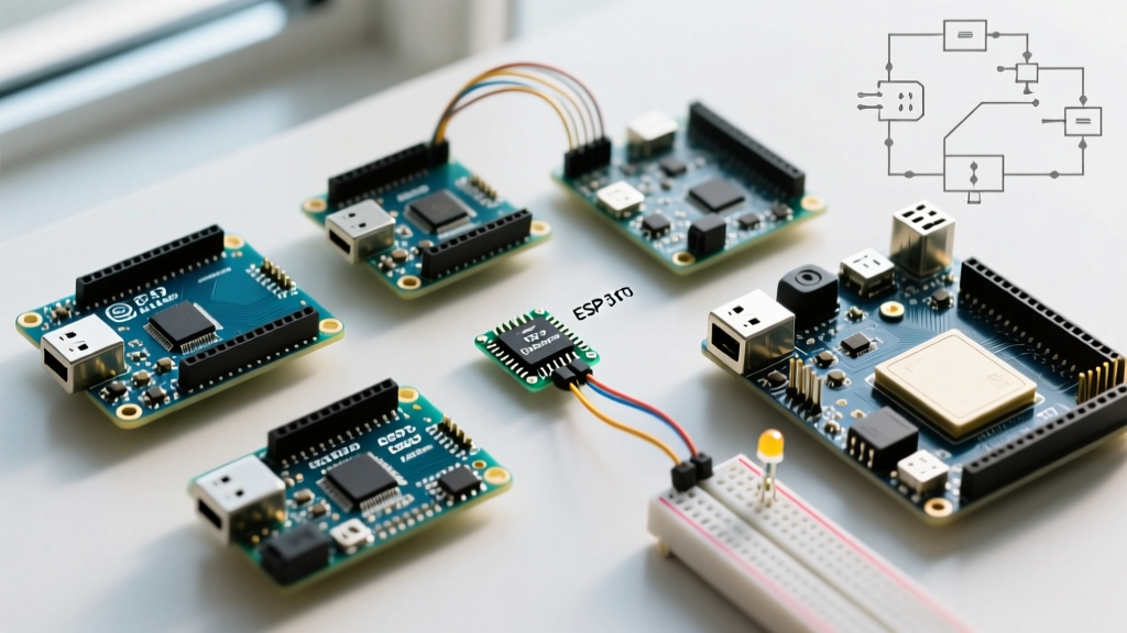
This guide compares the most popular official Arduino boards—Uno R4 Minima, Nano ESP32, Mega 2560, and Leonardo—strictly through the lens of error diagnosis. We will break down signature failure modes, exact IDE error strings, and hardware-level troubleshooting steps for each architecture.
The Diagnostic Matrix: Architecture vs. Failure Modes
| Board Model (2026 Standard) | Core MCU | USB Topology | Signature Error String | Primary Diagnostic Fix |
|---|---|---|---|---|
| Uno R4 Minima | Renesas RA4M1 (ARM) | Native USB via Bridge | No device found on cu.usbmodem... |
Double-tap Reset (0.5s interval) |
| Nano ESP32 | ESP32-S3 | Native USB (CDC/JTAG) | Brownout detector was triggered |
Check 3.3V rail & B0 boot pin |
| Mega 2560 | ATmega2560 (AVR) | ATmega16U2 Bridge | avrdude: stk500v2_ReceiveMessage(): timeout |
16U2 Loopback Test & Crystal check |
| Leonardo | ATmega32U4 (AVR) | Native USB (HID/CDC) | COM port vanishes post-compile | Manual bootloader trigger during upload |
1. Arduino Uno R4 Minima / WiFi: The Renesas ARM Bridge
The Uno R4 series (~$20-$27) replaced the classic ATmega328P with the Renesas RA4M1 ARM Cortex-M4. Unlike legacy AVRs, the R4 utilizes a complex USB bridge architecture. The most common error users face is USB enumeration failure after a bad sketch upload or power surge.
Diagnosing the 'No Device Found' Error
IDE Error:
No device found on cu.usbmodem14201orCOM port not found.
This occurs when the Renesas bootloader crashes or the USB bridge loses synchronization with the host OS. Because the R4 lacks a dedicated hardware auto-reset circuit tied to the DTR line in the same way the Uno R3 did, software resets can fail if the user sketch blocks the USB task scheduler.
- The Double-Tap Fix: Press the physical RESET button twice in rapid succession (within 0.5 seconds). This forces the RA4M1 into its ROM bootloader mode, exposing a new, stable COM port.
- Bridge Firmware Recovery: If the double-tap fails, the USB bridge firmware may be corrupted. According to the official Arduino Uno R4 Cheat Sheet, you must use the 'UNO R4 USB Firmware Updater' tool in the IDE to re-flash the bridge via the SWD pins.
2. Arduino Nano ESP32: Logic Levels and Brownouts
Priced around $21, the Nano ESP32 brings the dual-core power of the ESP32-S3 to the classic Nano footprint. However, its transition to native 3.3V logic is the primary source of hardware-level errors for users migrating from 5V AVR environments.
Diagnosing Brownout and Boot Mode Faults
Serial Monitor Output:
Brownout detector was triggered
IDE Error:Failed to connect to ESP32-S3: Timed out waiting for packet header
The ESP32-S3 is highly sensitive to voltage drops. If you connect a standard 5V I2C sensor without a bidirectional logic level converter, the internal pull-ups can back-feed current, or the sensor's 5V draw can sag the Nano's onboard 3.3V LDO regulator below the 3.1V brownout threshold.
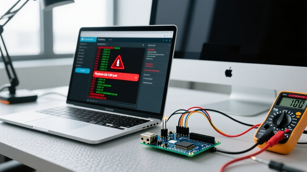
- Multimeter Verification: Probe the
3V3pin andGNDduring the upload sequence. If the voltage dips below 3.15V, the brownout detector triggers a continuous reset loop. - The GPIO0 (B0) Trap: If the board is stuck in a failed boot state, the ESP32-S3 requires GPIO0 to be pulled LOW during reset to enter the serial bootloader. On the Nano ESP32, this is mapped to the
B0button. HoldB0, pressRST, then releaseB0to force DFU mode. - Reference: Espressif's ESP32-S3 Hardware Guidelines explicitly warn against floating strapping pins, which can cause the MCU to boot into an unintended JTAG or SDIO mode, preventing standard UART uploads.
3. Arduino Mega 2560: The ATmega16U2 Bottleneck
The Mega 2560 (~$45) remains the workhorse for projects requiring massive I/O. Its architecture relies on a secondary microcontroller, the ATmega16U2, acting as a USB-to-Serial bridge. When uploads fail, the fault is often isolated to this bridge, not the main ATmega2560.
Diagnosing the stk500v2 Timeout
IDE Error:
avrdude: stk500v2_ReceiveMessage(): timeout
This specific error means the IDE is communicating with the 16U2 bridge, but the bridge cannot communicate with the main 2560 MCU via the UART0 (RX0/TX0) lines.
- The Loopback Test: To isolate the fault, bridge the
RX0andTX0pins on the main header. Open the Serial Monitor and type characters. If they echo back, the 16U2 bridge is healthy, meaning the ATmega2560 bootloader is corrupted or the main MCU is dead. If they do not echo, the 16U2 firmware is corrupted or the 16MHz crystal oscillator on the bridge circuit has failed. - Capacitor C1 Check: The auto-reset circuit relies on a 0.1µF capacitor between the 16U2 DTR line and the 2560 RESET pin. If this capacitor is damaged (common if external 12V sources are back-fed into the 5V rail), the board will compile but fail to reset the main MCU for uploading. Check continuity across C1 using a multimeter's capacitance mode; it should read ~100nF.
- Further Reading: The Arduino Mega Getting Started Guide details the exact pinout for the ICSP headers used to re-flash the 16U2 via an external ISP programmer if the bridge firmware is wiped.
4. Arduino Leonardo: The Vanishing COM Port
The Leonardo (~$20) uses the ATmega32U4, which features native USB capabilities. There is no secondary bridge chip; the main MCU handles both the user sketch and the USB CDC (Virtual COM Port) stack. This creates a unique and frustrating failure mode.
Diagnosing the Disappearing Port
If you upload a sketch that crashes immediately, disables interrupts, or enters an infinite while(1) loop in the setup() function, the USB stack is starved of CPU cycles. The host OS drops the COM port, and subsequent uploads will fail with a PORT not found error.
Hardware-Level Diagnostic Protocols for 2026
When software tricks fail, you must move to physical layer diagnostics. Keep these parameters in mind when comparing board health:
Voltage Rail Tolerances
- 5V Rail (Uno R4, Mega): Must measure between 4.85V and 5.15V under load. A reading of 4.6V indicates a failing polyfuse (PTC) on the USB power line, a common issue when drawing >400mA from USB-C ports without proper PD negotiation.
- 3.3V Rail (Nano ESP32): Must remain above 3.15V during WiFi transmission spikes (which can draw up to 350mA transiently). If it sags, add a 100µF tantalum capacitor directly across the 3V3 and GND pins on your breadboard.
Reset Line Oscilloscope Sniffing
If avrdude times out consistently across multiple cables and PCs, probe the RESET pin with an oscilloscope during an upload attempt. You should see a sharp drop to 0V (lasting ~2ms) when the IDE opens the serial port at 1200 baud. If the line remains at 5V, your host PC's USB driver is not asserting the DTR (Data Terminal Ready) signal, or the board's auto-reset capacitor is open-circuit.
Conclusion
Choosing the right microcontroller requires looking past the spec sheet. The Uno R4 offers immense processing power but requires understanding ARM bridge recovery. The Nano ESP32 provides wireless connectivity but demands strict 3.3V power discipline. The Mega 2560 offers unmatched I/O but introduces a secondary point of failure with its 16U2 bridge. By mastering these board-specific error diagnosis techniques, you can reduce hardware debugging time from hours to minutes, ensuring your 2026 embedded projects remain resilient in the field.