
The ATmega328P Trap: Why Standard Arduinos Fail at Audio
When makers first explore Arduino for audio projects, the default instinct is to reach for an Arduino Uno or Nano. This is a fundamental workflow error. The ATmega328P microcontroller is an 8-bit AVR running at 16 MHz. It lacks a true Digital-to-Analog Converter (DAC), forcing developers to rely on Pulse Width Modulation (PWM) via analogWrite(). This approach introduces a massive noise floor, requires aggressive analog low-pass filtering, and caps practical sample rates well below the 44.1 kHz required for CD-quality sound.
Furthermore, the 10-bit ADC maxes out around 9.6 kHz when using analogRead() in a standard loop, violating the Nyquist-Shannon sampling theorem for any frequencies above 4.8 kHz. To optimize your audio workflow in 2026, you must abandon 8-bit PWM and transition to 32-bit ARM Cortex-M architectures utilizing Inter-IC Sound (I2S) and Direct Memory Access (DMA).
Upgrading the Silicon: 32-Bit DSP and I2S Architectures
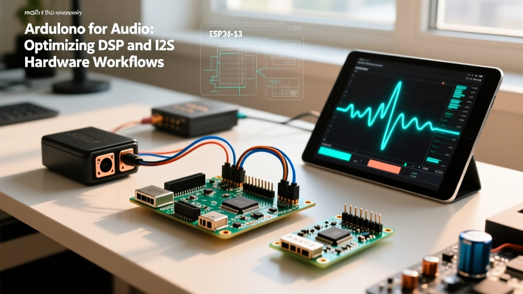
Optimizing your hardware stack is the first step in a professional audio workflow. I2S separates the clock signal from the data signal, eliminating the jitter inherent in standard SPI or I2C audio transmission. Below is a comparison of the top microcontrollers for advanced audio processing.
| Microcontroller | Architecture | Approx. Price (2026) | Audio Workflow Advantage | Best Use Case |
|---|---|---|---|---|
| Teensy 4.1 | ARM Cortex-M7 (600 MHz) | $38.00 | Native Audio Library, 128-sample block DSP | Real-time effects, synthesizers, granular delays |
| ESP32-S3 | Xtensa LX7 (240 MHz Dual-Core) | $12.00 | Dedicated I2S peripherals, 8MB PSRAM | Network audio streaming, I2S DAC playback |
| Arduino GIGA R1 | ARM Cortex-M7 (480 MHz) | $85.00 | Form-factor compatibility, dual DAC/ADC | High-channel count installations |
Workflow Optimization 1: Visual DSP Graphing
Writing raw DSP math (Fast Fourier Transforms, biquad filters) in C++ is prone to buffer overflow errors and phase miscalculations. The most optimized workflow for Arduino for audio relies on visual node-based routing. PJRC’s Teensy Audio System Design Tool allows you to visually patch inputs, mixers, filters, and outputs, automatically generating the C++ header code.
Understanding the 128-Sample Block
The Teensy Audio Library processes audio in blocks of 128 samples. At a 44.1 kHz sample rate, this equates to a processing latency of exactly 2.902 milliseconds per block. This is a critical metric for live instrument processing. If you chain five effects pedals (nodes) in your visual graph, the theoretical minimum latency remains 2.9 ms because the library processes the entire block through the chain before passing it to the I2S output buffer.
Pro Workflow Tip: Never usedelay()or blockingSerial.print()inside your main loop when using the Audio Library. The DMA handles the I2S transfer in the background, but blocking the main thread can cause the audio buffer to underrun, resulting in harsh digital popping.
Workflow Optimization 2: I2S DAC Integration & DMA
If you are using the ESP32-S3, you bypass the internal 8-bit DAC entirely by routing audio via I2S to an external DAC like the Texas Instruments PCM5102A (typically $5 on breakout boards). The ESP-IDF framework handles the DMA configuration, ensuring the CPU is free to handle Wi-Fi or Bluetooth tasks while the I2S peripheral streams audio directly from RAM.
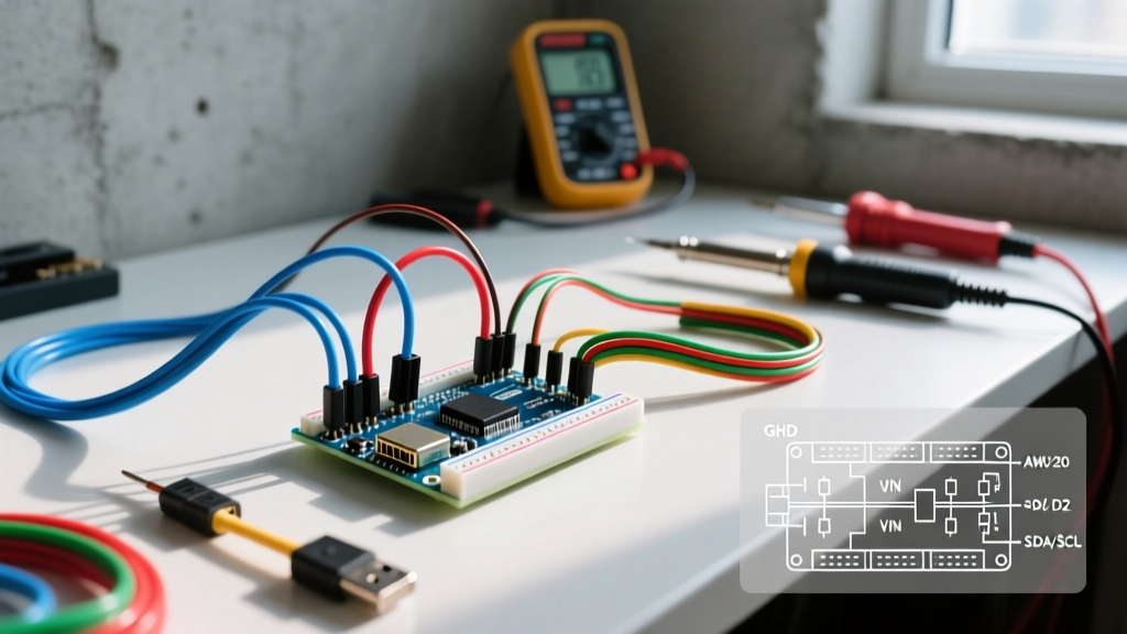
ESP32-S3 to PCM5102A Pinout Matrix
- BCK (Bit Clock): GPIO 14
- WS (Word Select / LRCK): GPIO 15
- DIN (Serial Data): GPIO 16
- VCC: 3.3V (Do not use 5V, the ESP32-S3 logic is 3.3V tolerant)
- GND: Common Ground
According to the Espressif I2S Driver Documentation, you must configure the I2S channel in standard mode, set the sample rate to 44100, and define the bit depth as 16. The DMA buffer should be set to at least 4 blocks of 1024 bytes to prevent Wi-Fi interrupt starvation from causing audio dropouts.
Workflow Optimization 3: High-Speed SD Streaming
Audio data is incredibly dense. One second of 16-bit, 44.1 kHz stereo audio consumes 176.4 KB of memory. Since microcontrollers have limited internal SRAM (the Teensy 4.1 has 1MB, but much is reserved for the audio engine and USB stack), you must stream directly from a MicroSD card.
Storage Hardware Requirements
Do not use cheap, unbranded SD cards. Audio streaming requires sustained sequential write/read speeds. You must use an SD card with an A1 or A2 Application Performance Class rating and a V30 Video Speed Class. The A2 rating is critical because it guarantees a minimum random read IOPS, which prevents buffer underruns when the SD card's internal controller performs background garbage collection.
For the software workflow, abandon the standard Arduino SD.h library. It is notoriously slow and blocks the CPU. Instead, use the SdFat library by Bill Greiman. Initialize the card with explicit SPI clock speeds:
SD.begin(chipSelect, SD_SCK_MHZ(24));
This forces the SPI bus to run at 24 MHz, maximizing the throughput of the hardware SPI peripheral.
Real-World Edge Cases and Hardware Debugging
Even with optimized code and 32-bit hardware, analog physics will introduce failure modes. Here is how to troubleshoot the most common edge cases in MCU audio design.
1. The USB Ground Loop Hum
Symptom: A persistent 60 Hz (or 50 Hz) hum and high-frequency whine that changes pitch when the CPU load spikes.
Cause: Powering your MCU via a PC USB connection creates a ground loop between the PC's switching power supply and your audio amplifier's ground.
Solution: Isolate the audio ground. For quick prototypes, power the MCU via a LiPo battery or an isolated DC-DC buck converter. For permanent installations, use an audio isolation transformer (like the T101) on the DAC output, or implement a digital isolator (like the ISO124) on the I2S data lines.
2. I2S Clock Drift and Pitch Shifting
Symptom: Audio plays back slightly sharp or flat, and after 10 minutes, you hear a loud 'pop' followed by a buffer skip.
Cause: The MCU's internal oscillator is driving the I2S BCLK, but it is not perfectly phase-locked to the DAC's internal PLL. Over time, the sample clocks drift apart.
Solution: Configure your MCU to act as the I2S slave and let the external DAC (or ADC) act as the master. High-end audio DACs use precision crystal oscillators that dictate the exact timing, forcing the MCU to adapt its DMA reads/writes to the DAC's clock, completely eliminating drift.
3. DAC Output Clipping and Decoupling
Symptom: Heavy distortion on bass transients, even when the digital signal is well below 0dBFS.
Cause: Inadequate decoupling capacitors on the DAC's analog power rails causing voltage sag during high-current bass notes.
Solution: Place a 100nF (0.1uF) X7R ceramic capacitor as physically close to the DAC's VCC pin as possible, paired with a 10uF tantalum or low-ESR aluminum electrolytic capacitor on the main power rail. This creates a low-impedance path for high-frequency transients, stabilizing the analog output stage.
Conclusion
Transitioning your Arduino for audio workflow from 8-bit PWM hacks to 32-bit I2S architectures and DMA-driven DSP routing is the difference between a noisy toy and a professional-grade audio instrument. By selecting the right silicon (Teensy 4.1 or ESP32-S3), utilizing visual DSP routing, and respecting analog decoupling and clock synchronization, you can achieve sub-3ms latency and pristine 16-bit audio fidelity.