
The Hidden Traps in Arduino Pin Out Diagrams
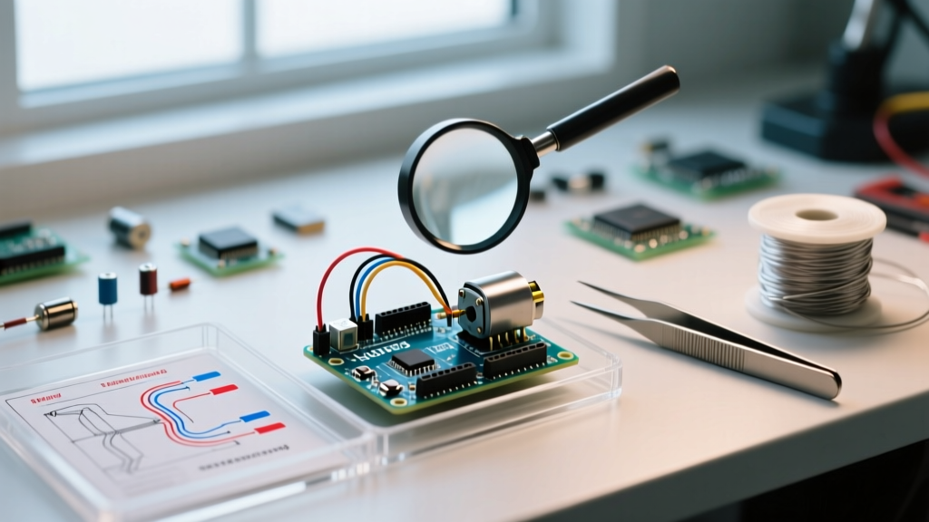
Every electrical engineer and maker has experienced the frustration of a perfectly compiled sketch that yields zero hardware response—or worse, releases the acrid smell of magic smoke. In 2026, with the maker ecosystem heavily transitioned toward advanced boards like the UNO R4 Minima and Nano ESP32, relying on legacy mental models of the classic Arduino pin out is a primary catalyst for hardware failure. Pinout diagrams often obscure the critical distinction between physical silkscreen labels, logical software mappings, and underlying silicon capabilities. This guide provides a rigorous diagnostic framework for identifying, isolating, and resolving the most destructive Arduino pin out wiring mistakes.
Top 4 Arduino Pin Out Errors & Diagnostic Workflows
Error 1: Analog vs. Digital Mapping Confusion (The A0-A5 Trap)
On the classic ATmega328P-based UNO R3, the analog pins A0 through A5 double as digital pins 14 through 19. A frequent error occurs when a developer writes pinMode(0, INPUT) intending to read A0, but inadvertently configures Digital Pin 0 (the hardware RX line), effectively killing serial communication and causing floating read states.
- Symptom:
Serial.print()outputs garbage data or halts; analog sensors read random noise (floating). - Diagnostic Step: Use the explicit analog aliases in your code. Always write
pinMode(A0, INPUT)rather than integer equivalents. If debugging a legacy codebase, inject aSerial.println(digitalRead(A0))vsdigitalRead(14)test to verify compiler mapping. - Hardware Check: Use a Fluke 117 multimeter in continuity mode. Probe the physical A0 header and trace it to the microcontroller's ADC pin to confirm physical continuity, bypassing software mapping entirely.
Error 2: I2C Bus Collisions on Alternate Pinouts
The I2C protocol requires strict adherence to SDA (data) and SCL (clock) lines. On the UNO R3, these are hardwired to A4 and A5. However, modern boards like the Nano ESP32 feature multiplexed pins where I2C can be mapped to almost any GPIO via software, but the physical silkscreen might still default to legacy expectations. Wiring an I2C OLED display to A4/A5 on a board where the default hardware I2C bus is routed to different pins will result in a hung bus.
- Symptom: The microcontroller freezes during
Wire.beginTransmission(), or the I2C scanner sketch returns zero devices. - Diagnostic Step: Run a standard I2C Scanner sketch. If no address is found, consult the specific board's 2026 datasheet. For the Nano ESP32, you may need to explicitly define the pins in software:
Wire.begin(A4, A5);. - Hardware Check: I2C requires pull-up resistors. Measure the voltage on the SDA and SCL lines with a multimeter. If you do not read the logic HIGH voltage (3.3V or 5V) when the bus is idle, you are missing the 4.7kΩ pull-up resistors, or the pins are misconfigured as push-pull outputs rather than open-drain.
Error 3: PWM Capability Assumptions (The Tilde Misunderstanding)
Pulse Width Modulation (PWM) is essential for motor control and LED dimming. The Arduino silkscreen denotes PWM-capable pins with a tilde (~). A common diagnostic failure is attempting to use analogWrite() on a non-PWM pin (like Digital Pin 2 on an UNO R3). The microcontroller will not throw a compilation error; instead, it defaults to a digital HIGH if the value is >127, and LOW if ≤127.
- Symptom: Motor runs at full speed or not at all; LED is fully bright or completely off, ignoring intermediate values.
- Diagnostic Step: Connect a Saleae Logic Analyzer or an oscilloscope to the pin. A true PWM pin will show a square wave with varying duty cycles. A non-PWM pin will show a flat DC line.
- Multimeter Trick: Set your multimeter to DC Voltage. Output
analogWrite(pin, 128). A true PWM pin will read approximately 2.5V (on a 5V board) due to the 50% duty cycle averaging. A non-PWM pin will read a solid 5V (because 128 > 127 triggers a digital HIGH).
Error 4: Overdrawing GPIO Current Limits
Perhaps the most fatal pin out error is treating a microcontroller GPIO as a power source. The ATmega328P has an absolute maximum rating of 40mA per pin, with a recommended operating limit of 20mA. Furthermore, the total current sourced through the VCC/GND pins cannot exceed 200mA. Wiring a 5V relay module or a high-power LED directly to a GPIO pin will cause severe voltage brownouts, erratic resets, or permanent silicon damage.
Expert Rule of Thumb: Never source more than 15mA continuously from a single Arduino GPIO. Always use a logic-level MOSFET (like the IRLZ44N) or a BJT (like the 2N2222) to switch high-current loads, using the Arduino pin only to drive the gate/base.
2026 Arduino Pin Out Reference Matrix
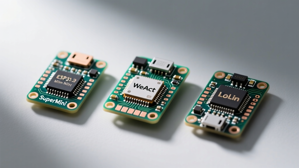
As the ecosystem evolves, assuming UNO R3 pinout rules apply to newer architectures is a critical error. Below is a diagnostic comparison matrix for the three most prevalent development boards in modern maker labs.
| Feature / Metric | UNO R3 (ATmega328P) | UNO R4 Minima (Renesas RA4M1) | Nano ESP32 (ESP32-S3) |
|---|---|---|---|
| Logic Level | 5V | 5V | 3.3V (5V tolerant on some) |
| Max Current per GPIO | 20mA (Recommended) | 8mA (Strict limit) | 40mA (Absolute max, 20mA safe) |
| Default I2C Pins | A4 (SDA), A5 (SCL) | A4 (SDA), A5 (SCL) | Software configurable (Default A4/A5) |
| PWM Resolution | 8-bit (0-255) | 8-bit to 14-bit configurable | 8-bit to 16-bit configurable |
| Common Pitfall | Exceeding 200mA total VCC limit | Assuming 20mA drive for legacy shields | Frying 3.3V logic with 5V sensors |
Note: When migrating a project from an UNO R3 to a Nano ESP32, failing to account for the 3.3V logic level threshold will result in the ESP32 failing to recognize 5V HIGH signals, or worse, damaging the ESP32-S3 silicon if the pin is not explicitly 5V tolerant.
Diagnostic Toolchain for Pin Out Verification
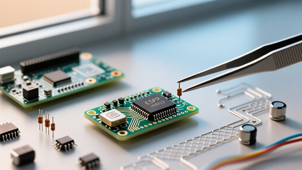
Relying solely on software debugging is insufficient for hardware-level pin out errors. A professional diagnostic bench should include:
- Digital Multimeter (e.g., Fluke 117): Essential for verifying continuity between the physical header and the microcontroller pad, checking for short circuits to ground, and measuring idle I2C pull-up voltages.
- Logic Analyzer (e.g., Saleae Logic 8): Invaluable for decoding SPI, I2C, and UART traffic. If your pin out is mapped incorrectly in software, the logic analyzer will immediately reveal missing clock pulses or corrupted data frames on the physical wire.
- Thermal Camera (e.g., FLIR One): If a pin out error causes a short circuit (e.g., configuring a pin as OUTPUT HIGH while it is physically wired to GND), a thermal camera will instantly highlight the overheating microcontroller trace before the silicon permanently fails.
Expert Troubleshooting FAQ
Why is my digital input reading random 1s and 0s when nothing is connected?
This is known as a "floating pin." A high-impedance input acts like an antenna, picking up electromagnetic interference from your environment. To diagnose and fix this, either wire a 10kΩ external pull-down resistor to GND, or enable the internal pull-up resistor in your code using pinMode(pin, INPUT_PULLUP). Remember that INPUT_PULLUP inverts the logic: the pin reads HIGH when disconnected and LOW when connected to GND.
My I2C sensor works on a breadboard but fails on a custom PCB. Is it a pin out error?
It is likely a signal integrity or pull-up issue rather than a strict pin mapping error. Breadboards add parasitic capacitance, but custom PCBs with long, unshielded I2C traces can suffer from cross-talk. Ensure your custom PCB routes SDA and SCL away from high-frequency SPI or PWM traces, and verify that 4.7kΩ pull-up resistors are physically populated on the board. For deeper analysis, consult the Arduino I2C Communication Documentation for bus capacitance limits.
Can I use the RX/TX pins (Digital 0 and 1) for standard GPIO?
Technically, yes, but it is highly discouraged for diagnostic reasons. Pins 0 and 1 are hardwired to the hardware UART interface connected to the USB-to-Serial bridge. Using them for standard GPIO (like driving a relay) will interfere with Serial.print() debugging and can prevent the bootloader from entering programming mode during sketch uploads. If you must use them, ensure all external circuits are disconnected during the upload sequence. For comprehensive foundational knowledge, refer to the Arduino Digital Pins Guide.
Conclusion
Mastering the Arduino pin out requires looking beyond the colorful diagrams found in beginner tutorials. True diagnostic expertise lies in understanding the electrical limitations, logical mappings, and architectural differences between legacy ATmega boards and modern ARM/ESP32 ecosystems. By employing systematic hardware verification—using multimeters, logic analyzers, and strict current-limiting practices—you can eliminate wiring errors, protect your components, and ensure robust, production-ready maker projects.