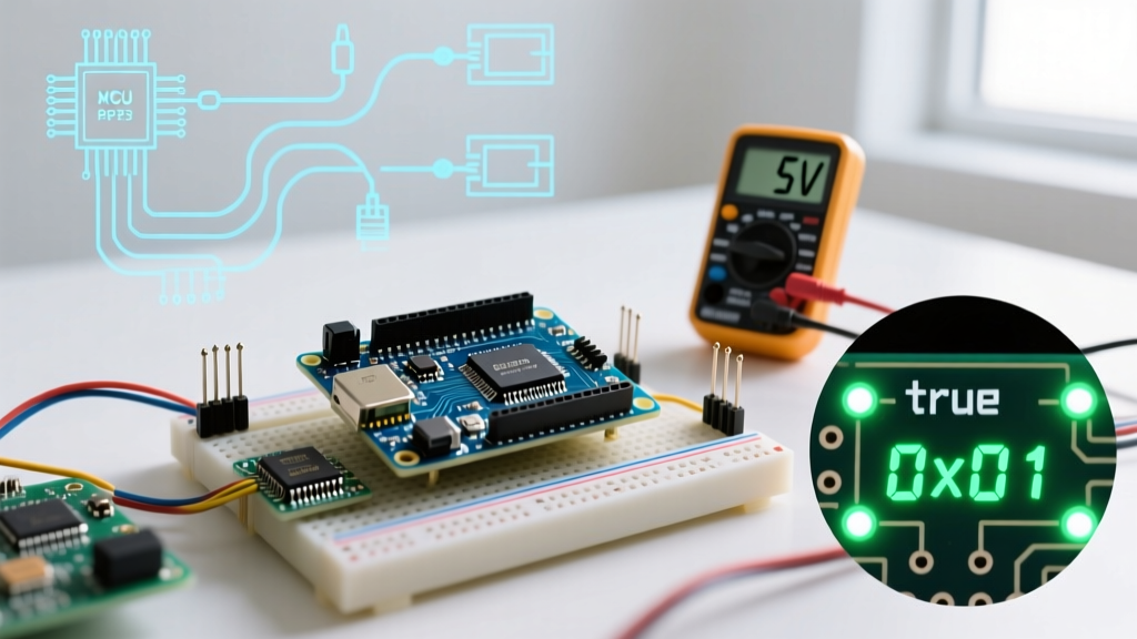

Quick Answer: In the Arduino ecosystem, the value ofbool trueis strictly defined as the integer1(specifically0x1in hexadecimal). However, during conditional evaluation, the compiler treats any non-zero value as logically true.
The Core Definition: What Is the Value of Arduino Bool True?
When configuring microcontrollers, understanding how the compiler interprets logical states is critical for writing bug-free firmware. If you are asking what is the value of Arduino bool true, the direct answer lies within the Arduino core source code. In the foundational Arduino.h header file, the boolean macros are explicitly defined as:
#define true 0x1
#define false 0x0
Because Arduino programming is fundamentally built on C++ (via the GCC compiler toolchain), the bool data type is a fundamental type introduced in the C++98 standard. According to the official C++ fundamental types documentation, a bool represents a binary state. When you assign bool myFlag = true;, the compiler allocates memory and stores the integer value 1.
However, a crucial distinction exists between assignment and evaluation. While true is strictly 1, the GCC compiler evaluates conditional statements (like if (x)) by checking if the value is non-zero. Therefore, if a sensor returns a value of 42, an if (sensorValue) statement will evaluate to logically true, even though 42 != 1.
Memory Allocation: The 1-Byte Reality
A common misconception among beginners is that because a boolean represents a single bit of information (on/off, 1/0), it only consumes one bit of RAM. This is incorrect. To understand how to configure memory-efficient sketches, you must understand hardware alignment.
Architecture Breakdown
- 8-bit AVR (ATmega328P, ATmega2560): The smallest addressable memory unit is 1 byte (8 bits). Therefore,
sizeof(bool)returns1. A single boolean variable consumes 8 bits of SRAM, wasting 7 bits. - 32-bit ARM / RISC-V (ESP32, SAMD21, STM32): Despite having 32-bit registers, the C++ standard mandates that
sizeof(bool)is at least1byte. On an ESP32-C6, a standaloneboolstill consumes 1 byte of SRAM.
For a comprehensive look at how 8-bit architectures handle data types and memory mapping, the AVR Libc User Manual provides exhaustive details on register allocation and SRAM boundaries.
Semantic Configuration: true vs. HIGH vs. 1
While true, HIGH, and 1 all share the exact same underlying hexadecimal value (0x1), using them interchangeably is a hallmark of poor firmware configuration. Strict typing and semantic correctness prevent compiler warnings and logical errors.
| Macro / Value | Hex Value | Intended Use Case | Compiler Strictness |
|---|---|---|---|
true / false |
0x1 / 0x0 |
Logical operations, state flags, if/while conditions. |
Strictly typed for bool variables. |
HIGH / LOW |
0x1 / 0x0 |
Physical pin states (digitalWrite, digitalRead). |
Expected by Arduino I/O functions. |
1 / 0 |
0x1 / 0x0 |
Mathematical calculations, bitwise masking, array indexing. | Triggers -Wconversion warnings if assigned to bool. |
Why Mixing HIGH and true Causes Issues
Technically, writing digitalWrite(LED_PIN, true); will compile and illuminate the LED because the underlying value is 1. However, if you enable strict compiler warnings in the Arduino IDE (via preferences.txt), the GCC compiler will flag this as a type mismatch. HIGH is an enumeration specifically mapped to hardware pin states, whereas true is a logical abstraction. Always configure your code to use HIGH/LOW for hardware pins and true/false for software logic.
Advanced RAM Optimization: Bitfields
If your project requires tracking dozens of configuration flags—such as in a complex IoT state machine or a custom PID controller—declaring fifty individual bool variables will consume 50 bytes of precious SRAM. On an ATmega328P with only 2,048 bytes of SRAM, this is a significant overhead.
To solve this, advanced firmware engineers use C++ Bitfields inside structs. This forces the compiler to pack multiple boolean values into a single byte.
struct SystemFlags {
  bool isArmed : 1;
  bool isFaulted : 1;
  bool wifiConnected : 1;
  bool sensorCalibrated : 1;
  bool motorEnabled : 1;
  // 5 bits used, 3 bits padding. Total size: 1 Byte!
};

SystemFlags configFlags;

void setup() {
  configFlags.isArmed = true;
  configFlags.wifiConnected = false;
}
By configuring your booleans this way, you reduce the memory footprint of 8 separate flags from 8 bytes down to a single 1-byte struct. This is a critical optimization technique for memory-constrained environments.
Edge Cases and Troubleshooting Boolean Logic
When configuring complex logic gates in your sketch, misunderstanding how the Arduino evaluates bool true can lead to catastrophic failure modes. Here are the most common edge cases:
1. Bitwise AND (&) vs. Logical AND (&&)
A frequent configuration error occurs when developers use the bitwise AND operator instead of the logical AND operator in conditional statements.
if (sensorA && sensorB)evaluates the logical truth of both variables. If both are non-zero, it returnstrue(1).if (sensorA & sensorB)performs a bitwise comparison of the underlying binary values. IfsensorAis2(binary0010) andsensorBis1(binary0001), the bitwise AND results in0(false), even though both variables are logically non-zero.
2. Serial Monitor Output Configuration
When debugging, using Serial.print(myBool); will output 1 or 0 to the serial monitor, not the text "true" or "false". If your debugging workflow requires textual confirmation, you must configure a custom print function or use the ternary operator:
Serial.println(myBool ? "True" : "False");3. The Inversion Bug
When using the logical NOT operator (!), remember that !true strictly equals false (0). However, !5 also equals false (0). If you are passing raw ADC or sensor data through a NOT operator expecting it to map cleanly to 1, your logic will fail. Always cast or evaluate raw data into a strict bool before applying inversion operators.
Summary Matrix
To ensure your microcontroller configurations are robust, refer to this quick summary matrix regarding boolean behaviors in the Arduino IDE:
| Operation | Resulting Value | Memory Impact |
|---|---|---|
bool x = true; |
1 (0x01) |
1 Byte (8 bits) |
bool y = 42; |
1 (Compiler casts non-zero to 1) |
1 Byte (8 bits) |
sizeof(bool) |
1 |
N/A |
true == HIGH |
true (1 == 1) |
N/A |
Understanding what is the value of Arduino bool true extends far beyond simply knowing it equals 1. By mastering how the GCC compiler allocates memory, how bitwise operations interact with logical states, and how to implement struct bitfields, you can write highly optimized, professional-grade firmware for any microcontroller platform. For further reading on standard Arduino syntax and data types, consult the Official Arduino Language Reference.