
Beyond the Blink: Engineering a Reliable Prototyping Workflow
When learning how to use breadboard with arduino setups, most beginners focus solely on making an LED blink or reading a basic sensor. However, as your projects scale to include multiple I2C sensors, SPI displays, and high-current actuators, a disorganized breadboard becomes a liability. Intermittent connections, voltage drops, and parasitic capacitance can introduce hours of phantom debugging. In 2026, with the release of high-performance boards like the Arduino Uno R4 WiFi and the Nano ESP32, treating your solderless breadboard as a precise engineering tool rather than a toy is critical for workflow optimization.
This guide bypasses basic tutorials and focuses on advanced layout strategies, power distribution physics, and wire management techniques to drastically reduce your prototyping iteration time.
Hardware Selection: The Hidden Cost of Contact Resistance
Not all breadboards are manufactured equally. The internal leaf-spring contacts dictate the reliability of your entire circuit. Cheap, unbranded breadboards (often sold in bulk on Amazon for under $1.50 each) frequently suffer from inconsistent spring tension and thin metal plating. This results in contact resistances that can exceed 100mΩ per node.
For professional workflow optimization, invest in name-brand boards like the SparkFun PRT-12002 (approximately $6.50) or the Elegoo MB-102. According to the SparkFun Breadboard Tutorial, high-quality boards maintain a contact resistance of roughly 10mΩ to 20mΩ and are rated for 2A per node, though best practices dictate keeping continuous draw below 1A to prevent thermal warping of the ABS plastic housing.
The 22 AWG Solid Core Mandate
Never use stranded wire for breadboard tie points. Stranded wires fray, jamming the internal spring clips and permanently damaging the breadboard. Always use 22 AWG solid core wire. When stripping the wire, remove exactly 6mm (1/4 inch) of insulation. Stripping more than 6mm leaves bare copper exposed to accidental shorting; stripping less forces the plastic insulation into the contact clip, creating an open circuit that is notoriously difficult to troubleshoot.
Power Distribution: Avoiding the Voltage Drop Trap
The most common point of failure in complex Arduino prototypes is inadequate power routing. The Arduino Uno R4 Minima can deliver significantly more current via its USB-C PD negotiation than the older Uno R3, but your breadboard's power rails will bottleneck this if not managed correctly.
Long breadboard power rails have inherent trace resistance. If you draw 800mA through a standard 830-tie-point board to power a strip of WS2812B LEDs, you will experience a measurable voltage drop from one end of the rail to the other, leading to flickering or microcontroller brownouts.
| Breadboard Tier | Max Safe Continuous Current | Estimated Rail Resistance (Full Length) | Voltage Drop at 500mA |
|---|---|---|---|
| Premium (SparkFun/Bus Pirate) | 1.0A - 1.5A | ~0.15 Ω | 0.075V |
| Mid-Tier (Elegoo MB-102) | 0.75A - 1.0A | ~0.30 Ω | 0.15V |
| Budget Clones (Generic) | 0.3A - 0.5A | ~0.80 Ω+ | 0.40V+ (Brownout Risk) |
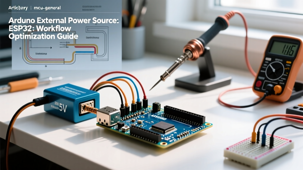
Workflow Optimization Tip: For projects drawing over 500mA, abandon the breadboard's internal power rails for the main load. Use a dedicated external power supply module (like the MB-V2) and route high-current ground and VCC lines directly to the components using thicker 18 AWG jumper wires, reserving the breadboard rails strictly for logic-level signals and microcontroller power.
Strategic Wire Management and Color-Coding
A chaotic nest of multi-colored Dupont wires is a debugging nightmare. Optimizing your physical layout speeds up troubleshooting by allowing you to trace circuits visually. Adopt a strict color-coding standard aligned with industry norms, as referenced in the Arduino Official Breadboard Guide:
- Red: 5V Power
- Black: Ground (GND)
- Orange: 3.3V Power
- Yellow: Digital Signals / GPIO
- Blue: Analog Signals
- Green: I2C / SPI Data Lines
Ditch the loose, flexible male-to-male Dupont jumper wires for signal routing. They act as antennas, picking up electromagnetic interference (EMI), and their length creates clutter. Instead, use pre-formed solid-core jumper wire kits (such as the MakerHawk or SparkFun assortments). These lay flat against the breadboard surface, keeping the profile low and allowing you to easily probe adjacent nodes with a multimeter without accidentally shorting neighboring pins.
Signal Integrity: Managing Parasitic Capacitance
Solderless breadboards introduce parasitic capacitance between adjacent rows and tie points, typically ranging from 2pF to 5pF per node. While this is irrelevant for a 1Hz blinking LED, it becomes a critical failure mode when using the Arduino Nano ESP32 for high-speed SPI communication or fast PWM generation.
Engineering Insight: If you are routing a 10MHz SPI clock line across a breadboard, the parasitic capacitance combined with the inductance of long jumper wires will cause signal ringing and edge degradation, resulting in corrupted data on your SD card or TFT display.
To mitigate this in a breadboard environment:
- Keep high-speed signal traces (SPI CLK, MOSI) under 5cm in physical length.
- Place the target peripheral (e.g., an ILI9341 display) immediately adjacent to the Arduino's SPI header pins.
- Add a 220Ω series termination resistor at the source pin to dampen high-frequency ringing caused by the breadboard's reactive impedance.
Debugging Workflows and Maintenance
Even with perfect technique, oxidation and mechanical wear will eventually cause intermittent faults. When a circuit fails, follow this optimized diagnostic workflow before rewriting your firmware:
1. The Probe-Point Layout Strategy
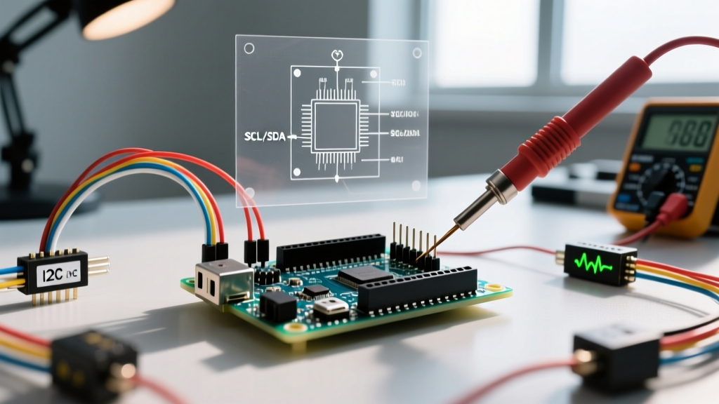
When placing components like DIP ICs (e.g., an ATmega328P or a 555 timer) across the center trench, intentionally leave the adjacent row completely empty. This dedicated 'probe row' allows you to insert Fluke or AN8008 multimeter probes securely without slipping and shorting the IC pins.
2. Contact Rehabilitation
Component leads and jumper wires oxidize over time, creating a high-resistance barrier. If you suspect a bad connection, do not simply wiggle the wire. Remove the wire, inspect the tip for black oxidation, and clean it. For the breadboard contacts themselves, a single spray of DeoxIT D5 contact cleaner (approx. $20 per can) into the affected nodes will dissolve oxidation and restore optimal spring-clip conductivity. This single maintenance step can extend the life of a premium breadboard by years.
3. The Voltage Drop Test
Instead of using a continuity beep test (which only checks for a basic connection), use your multimeter's DC voltage mode. Power the circuit and measure the voltage directly at the microcontroller's 5V pin, then measure it at the VCC pin of your furthest sensor. A difference greater than 0.1V indicates a high-resistance fault in the breadboard's power rail or jumper wires, instantly isolating the physical layer as your bug source.
Conclusion
Mastering how to use breadboard with Arduino environments is less about memorizing pinouts and more about controlling the physical variables of your prototype. By selecting low-resistance hardware, enforcing strict wire management, respecting high-frequency parasitic limits, and maintaining your contacts, you transform the breadboard from a source of frustration into a highly reliable, rapid-iteration engineering platform.