
The Hidden Culprit: When Your Enclosure Causes the Fault
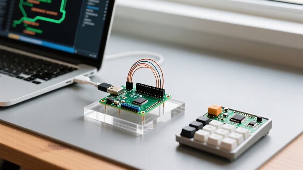
As makers and engineers transition from breadboard prototypes to deployed, ruggedized IoT field devices in 2026, the physical enclosure is often treated as a mere cosmetic afterthought. However, a poorly selected or improperly assembled arduino case is one of the most frequent sources of "phantom" hardware errors. These are the maddening, intermittent faults—random watchdog resets, I2C bus collisions, unexplained sensor drift, and sudden WiFi dropouts—that defy standard software debugging.
When your sketch compiles perfectly but the hardware behaves erratically in the field, the physical environment inside the enclosure is your primary suspect. This guide provides a deep-dive diagnostic framework for identifying and resolving electrical, thermal, RF, and mechanical errors introduced by your enclosure choice.
1. Electrical Diagnosis: Conductive Enclosures and the Polyfuse Trap
The most catastrophic phantom errors stem from unintended electrical contact between the PCB and the enclosure. While standard injection-molded ABS or PETG cases are naturally insulating, the modern maker ecosystem heavily favors aluminum extrusions (like the MakerBeam XL series) and conductive 3D printing filaments (such as Proto-pasta Conductive PLA, which retails around $45/kg).
The Anodization Scratch Failure Mode
Aluminum enclosures rely on a thin anodized layer for electrical insulation. However, during assembly, driving self-tapping screws or forcing tight-tolerance PCBs into extruded slots can scratch this layer, exposing raw, highly conductive aluminum. If a 5V trace or digital pin on your Arduino Uno R3 or Nano makes contact with a scratched interior wall, it creates a dead short.
Rather than immediately destroying the ATmega328P microcontroller, the board's onboard PTC resettable fuse (typically a Bourns RXEF050 rated for 500mA hold current) will trip. When the polyfuse trips, its resistance spikes, causing the board's operating voltage to drop to roughly 4.1V. This triggers the microcontroller's internal Brown-Out Detector (BOD), resulting in a continuous reboot loop.
Diagnostic Step: If your serial monitor outputs
avrdude: stk500_recv() programmer is not respondingor the board continuously resets when placed inside the case, use a digital multimeter in continuity mode. Probe the GND pin and the raw aluminum interior. Any reading below 10 ohms indicates a scratch-induced short.
The Fix: Polyimide and Nylon Isolation
Never rely solely on anodization for insulation. Line the interior contact points with Kapton tape (polyimide film), which offers dielectric strength up to 7,000V and thermal stability up to 400°C. Furthermore, replace all metallic M2.5 or M3 standoffs with glass-filled nylon standoffs, which cost approximately $4 for a pack of 100 on standard component supplier sites.
2. Thermal Diagnosis: Voltage Regulator Throttling and Sensor Drift
Sealing an Arduino inside an IP-rated case (like an IP65 polycarbonate enclosure) traps heat. The classic Arduino Uno R3 utilizes an NCP1117ST50T3G linear voltage regulator to step down external barrel-jack voltage (7-12V) to 5V. Linear regulators dissipate excess voltage as heat. If you power the board with 12V and draw 200mA, the regulator must dissipate 1.4 Watts of thermal energy.
Thermal Resistance of Common Enclosure Materials
In a sealed environment without active airflow, the internal ambient temperature rises until thermal equilibrium is reached. If the internal ambient exceeds 85°C, the NCP1117's internal thermal shutdown circuit triggers at 150°C junction temperature, cutting power to the 5V rail instantly.
| Case Material | Thermal Conductivity (W/m·K) | Max Safe Internal Ambient (No Vents) | Common Failure Symptom |
|---|---|---|---|
| PLA (3D Printed) | 0.13 | 55°C (Material softens) | Case warping, standoff pull-out |
| ABS (Injection Molded) | 0.17 | 80°C | BOD resets, I2C sensor drift |
| Polycarbonate (IP-Rated) | 0.20 | 110°C | Regulator thermal shutdown |
| Die-Cast Aluminum | 120.0 - 200.0 | 130°C (Acts as heatsink) | RF detuning (see Section 3) |
Diagnosing I2C Sensor Drift
Thermal errors don't always cause hard resets; often, they manifest as data corruption. If you are logging environmental data using a BME280 sensor mounted on the same PCB as the heat-generating voltage regulator, the localized thermal gradient will cause the temperature and humidity readings to skew by +3°C to +8°C. According to the official Arduino Uno Rev3 hardware documentation, maintaining proper thermal headroom is critical for analog-to-digital converter (ADC) accuracy. The Fix: Calculate the required passive ventilation. For every 1W of dissipated power, provide at least 15 square centimeters of cross-ventilation (intake at the bottom, exhaust at the top) to establish a natural convection chimney effect.
3. RF Diagnosis: Antenna Detuning in Wireless Deployments
With the massive adoption of the ESP32-S3 and Arduino Nano 33 IoT for edge computing, wireless reliability is paramount. A common and devastating mistake is housing a board with an onboard PCB trace antenna inside a die-cast aluminum enclosure, such as the industry-standard Hammond 1590B series.
Metal enclosures act as a Faraday cage, but the more insidious issue is antenna detuning. If the PCB antenna is placed within 5mm to 10mm of a conductive case wall, the parasitic capacitance shifts the resonant frequency of the antenna away from the 2.4 GHz Wi-Fi/Bluetooth band.
The VSWR Metric and Signal Loss
In a properly tuned system, the Voltage Standing Wave Ratio (VSWR) is close to 1.5:1. When detuned by a nearby metal arduino case, the VSWR can spike above 5:1, meaning the majority of the RF energy is reflected back into the ESP32's transceiver rather than radiated.
- Symptom: RSSI (Received Signal Strength Indicator) drops from a healthy -45 dBm to an unusable -88 dBm, resulting in continuous MQTT broker disconnects.
- Diagnostic Tool: Use the ESP32's built-in
WiFi.RSSI()function to log signal strength. If the RSSI drops by more than 15 dBm the moment the metal lid is screwed on, you have severe detuning. - The Fix: Follow the Espressif Hardware Design Guidelines by maintaining a strict 5mm keep-out zone around the antenna. If a metal case is mandatory for EMI shielding, you must disable the onboard antenna via resistor pad switching and route the RF signal to an external SMA connector using a u.FL pigtail.
4. Mechanical Diagnosis: Tolerance Stacking and USB Faults
Intermittent serial connection drops and "USB device not recognized" errors in the Windows Device Manager are frequently blamed on faulty CH340 or ATmega16U2 USB-serial chips. However, the root cause is often mechanical stress induced by the arduino case.
Cheap, mass-produced injection-molded enclosures suffer from "tolerance stacking." If the PCB mounting bosses are molded 0.5mm too high, and the USB port cutout is 0.5mm too low, forcing the board into the case applies a constant downward sheer stress on the USB Type-B or Type-C surface-mount connector. Over time, thermal expansion and contraction in the field cause the microscopic solder joints connecting the USB shield to the PCB ground plane to crack.
Diagnostic Step: Remove the board from the case and plug it directly into your PC. If the serial connection stabilizes instantly, the case is applying mechanical torque. Use digital calipers to measure the distance from the case port cutout to the internal mounting shelf, and compare it against the PCB's physical dimensions. Use a needle file to expand the case cutout by 1mm to relieve the shear stress.
The 2026 Enclosure Diagnostic Flowchart
Before rewriting your firmware or replacing your microcontroller, run this physical diagnostic checklist to isolate enclosure-induced faults:
- The Bare-Bench Test: Does the error persist when the PCB is completely removed from the case and resting on a non-conductive silicone mat? If no, the case is the culprit.
- The Continuity Sweep: With the board powered off and seated in the case, probe all exposed vias and header pins against the enclosure walls. Look for shorts.
- The Thermal Camera Pass: Power the board inside the sealed case for 30 minutes. Use a thermal imager (like the FLIR One) to scan the exterior. If the exterior remains at room temperature while the internal voltage regulator is burning hot, your enclosure lacks thermal mass or ventilation.
- The RF Delta Test: Log wireless RSSI for 5 minutes with the lid off, then 5 minutes with the lid on. A delta greater than 10 dBm requires an external antenna solution.
By treating the arduino case as an active electrical and thermal component rather than a passive box, you can eliminate the phantom hardware errors that plague field-deployed maker projects.