
The Architecture Divide: Hardware UART vs. Native USB CDC
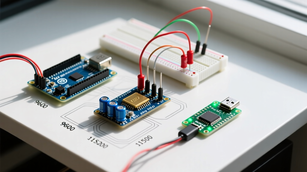
For over a decade, Serial.begin(9600) has been the universal handshake for microcontroller development. However, as we navigate the hardware landscape of 2026, treating the Arduino Serial API as a monolithic standard is a critical mistake. The underlying behavior of the Serial object changes drastically depending on whether your board routes data through a dedicated hardware UART bridge or a native USB Communication Device Class (CDC) interface.
When you call Serial.begin() on a classic Arduino Uno R3 (ATmega328P), you are configuring the physical hardware UART0 peripheral. The baud rate parameter directly manipulates the UBRR (USART Baud Rate Register) clock divider. The data is then pushed to an ATmega16U2 coprocessor, which translates the UART signals into USB packets for your PC.
Conversely, on modern native-USB boards like the Arduino Zero (SAMD21), Raspberry Pi Pico (RP2040), or the ESP32-S3, the Serial object maps to a virtual USB CDC port. In this scenario, the baud rate parameter passed to Serial.begin() is completely ignored by the USB stack. The USB host (your PC) and the device negotiate data transfer rates at the USB packet level (typically 12 Mbps for Full-Speed USB), rendering the 9600 or 115200 argument functionally obsolete for the primary serial console. However, this same function call is strictly required to configure the secondary hardware UART pins (e.g., Serial1 on the RX/TX pins).
Baud Rate Compatibility Matrix (2026 Hardware Standards)
Understanding the physical limits of your MCU's UART peripheral is vital when interfacing with external modules like GPS receivers, RS-485 transceivers, or legacy industrial equipment. Below is a compatibility matrix detailing the real-world limits of common maker architectures.
| MCU Family | Serial Mapping | Max Stable Baud (Hardware UART) | USB CDC Behavior | Bootloader Interference |
|---|---|---|---|---|
| AVR (ATmega328P) | Hardware UART0 | 500,000 (with U2X bit) | N/A (Bridged via 16U2) | Optiboot holds TX for ~300ms |
| SAMD (SAMD21G18) | Native USB CDC | 3,000,000 (SERCOM pads) | Baud parameter ignored | Bootloader CDC enumeration delay |
| ESP32 (Xtensa LX6) | Hardware UART0 | 5,000,000 | N/A (Bridged via CP2102/CH340) | ROM bootloader prints at 74880 baud |
| RP2040 (Cortex-M0+) | Native USB CDC | 921,600 (PL011 blocks) | Baud parameter ignored | UF2 bootloader mounts as USB drive |
Note: While the ESP32 hardware supports up to 5 Mbps, the ubiquitous CH340C USB-to-UART bridge chips found on $4 clone boards often bottleneck at 1.5 Mbps or exhibit packet loss above 921,600 baud due to internal buffer overruns.
The while(!Serial); Compatibility Trap
One of the most frequent points of failure when porting code from an AVR-based Uno to an ARM-based Nano 33 IoT or RP2040 Pico is the serial initialization sequence. On native USB boards, the USB CDC connection is not established the millisecond the board receives power. The host OS must enumerate the USB device, load the CDC driver, and open the virtual COM port.
If your sketch immediately fires Serial.println("System Ready"); after Serial.begin(115200); on a native USB board, that data is silently dropped into the void because the USB endpoint is not yet connected to a host listener.
The AVR vs. ARM Execution Flow
- AVR (Uno/Mega): The hardware UART is instantly active.
while(!Serial);is dangerous here; if the board is powered by a battery without a PC connected, theSerialobject will never evaluate to true, and your sketch will hang indefinitely in an infinite loop. - Native USB (Zero/Pico/Leonardo): The
while(!Serial);block is mandatory if you need to capture the first few lines of boot debug data. However, it introduces a new failure mode: if deployed in a standalone, headless environment (no USB cable attached), the sketch will hang waiting for a USB host that will never arrive.
Expert Workaround: To write universally compatible code that doesn't hang in headless deployments but still captures boot logs when tethered, use a non-blocking timeout wrapper:Serial.begin(115200); unsigned long startMillis = millis(); while (!Serial && (millis() - startMillis < 2500)) { delay(10); // Wait up to 2.5 seconds for USB CDC enumeration }
Advanced Configuration: Data Bits, Parity, and Stop Bits
The standard Arduino Serial.begin() reference documents the secondary parameter for serial configuration, defaulting to SERIAL_8N1 (8 data bits, No parity, 1 stop bit). However, cross-platform compatibility breaks down when you attempt to use parity for industrial noise rejection.
When interfacing with Modbus RTU sensors or DMX512 lighting controllers, you often need SERIAL_8E1 (Even parity) or SERIAL_8N2 (2 stop bits).
- AVR & SAMD: Handle parity generation and checking entirely in the hardware UART peripheral. The CPU overhead is zero, and framing errors are caught automatically.
- ESP32: The ESP-IDF UART peripheral supports hardware parity, but early versions of the Arduino-ESP32 core had bugs where passing
SERIAL_8E1toSerial.begin()failed to update the RS485 mode registers correctly. Always ensure you are using ESP32 Core v3.0.x or newer for reliable parity support. - Software Serial: If you are forced to use
SoftwareSerialon an AVR because the hardware UART is occupied, be aware thatSoftwareSerialdoes not support parity or configurable stop bits. It is strictly locked to 8N1.
Real-World Edge Cases and Failure Modes
1. ESP32 UART0 Strapping Pin Conflicts
On the original ESP32 and ESP32-C3, the primary hardware UART0 is hardwired to GPIO1 (TX) and GPIO3 (RX). These pins double as "strapping pins" used by the ROM bootloader to determine boot modes. If your external circuit pulls GPIO3 HIGH during a reset, the ESP32 will enter the serial bootloader and halt your sketch. Furthermore, upon every hard reset, the ESP32 ROM bootloader outputs a boot log at exactly 74880 baud. If your serial monitor is set to 115200, this boot log will appear as garbage characters (e.g., ets Jun 8 2016 00:22:57\r\nrst:0x1). This is not a bug; it is a hardware-level output that occurs before Serial.begin() is even executed.
2. AVR Crystal Mismatch and Clock Drift
The ATmega328P calculates its baud rate based on the assumption of a perfect 16.000 MHz external crystal. In reality, cheap ceramic resonators found on sub-$3 clone boards can have a tolerance of ±0.5% to ±1.0%. When you push the baud rate to 115200, the math yields a UBRR value of 8 (with U2X enabled), resulting in an actual baud rate of 117,647. This introduces a +2.1% error. Combined with a ±1% crystal drift and the tolerance of your PC's USB-UART bridge, the total error can exceed the ±4% threshold required for reliable UART communication, resulting in intermittent framing errors and corrupted bytes. If you experience random data corruption at 115200 baud on an AVR, drop to 57600 or 38400, where the clock divider math yields a much lower error margin.
3. RP2040 PL011 vs. PIO UART
The RP2040 datasheet reveals that the chip contains two dedicated PL011 UART blocks and a Programmable I/O (PIO) subsystem. By default, Serial1 and Serial2 map to the hardware PL011 blocks. However, if you run out of pins or need a non-standard baud rate (like the 104.17 baud required by some legacy automotive K-Line protocols), the RP2040 Arduino core allows you to instantiate a PIO-based UART. While highly flexible, PIO UARTs consume slightly more CPU cycles and can introduce microsecond-level jitter compared to the dedicated PL011 silicon.
Summary Checklist for Cross-Platform Serial Code
To ensure your sketches compile and function flawlessly across the fragmented 2026 MCU ecosystem, adopt this initialization checklist:
- Identify the USB Architecture: Determine if
Serialis a hardware UART or USB CDC. Adjust your boot-time delays accordingly. - Implement Timeout Wrappers: Never use a blocking
while(!Serial);without a millisecond timeout to prevent headless deployment hangs. - Respect the Bridge Bottleneck: Do not attempt to push >1 Mbps through an ESP32 dev board equipped with a CH340C bridge; upgrade to a board with a CP2102N or native USB (ESP32-S3).
- Verify Strapping Pins: Ensure no external sensors or pull-up resistors are attached to UART0 TX/RX pins on ESP32 or ESP8266 boards that might interfere with the bootloader sequence.
- Calculate Baud Errors: For AVR boards, stick to 38400, 57600, or 115200. Avoid arbitrary values like 100000, which will result in massive clock divider rounding errors.