
Every maker has experienced the frustration of a seemingly bricked microcontroller, only to realize the culprit was a substandard cable. As of 2026, with the widespread adoption of USB-C boards like the Arduino Uno R4 WiFi and Nano ESP32, understanding the technical nuances of arduino cables is more critical than ever. A cable is not just a wire; it is a transmission line with specific capacitance, resistance, and shielding characteristics that directly impact serial communication and power delivery.
This quick-reference FAQ cuts through the fluff to provide hard data, exact specifications, and actionable troubleshooting steps for your USB and jumper cables.
Quick Reference: USB Connector Types by Board
Before troubleshooting, verify you are using the correct physical interface and that your cable supports the required data protocols. Below is the definitive matrix for modern and legacy Arduino boards.
| Board Model | USB Connector | Onboard Serial Chip | Required Cable Spec |
|---|---|---|---|
| Uno R3 / Mega 2560 | USB Type-B | ATmega16U2 | USB 2.0 A-to-B (Data + Power) |
| Uno R4 Minima / WiFi | USB Type-C | Renesas RA4M1 / ESP32-S3 | USB 2.0 C-to-C or A-to-C (Data) |
| Nano Classic | Mini-B | FT232RL or CH340G | USB 2.0 A-to-Mini-B (Data) |
| Nano ESP32 | USB Type-C | ESP32-S3 (Native USB) | USB 2.0 C-to-C (Data + 5V/3A) |
| Arduino MKR Series | Micro-B | SAMD21 Native USB | USB 2.0 A-to-Micro-B (Data) |
FAQ: The "Charge-Only" Cable Trap
Why does my board power on but won't show up in the IDE?
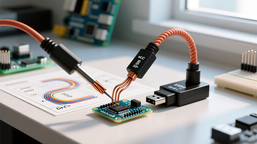
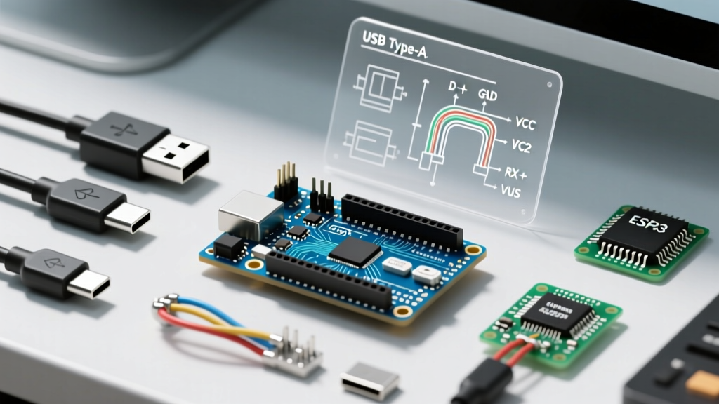
The most common point of failure in MCU prototyping is using a "charge-only" cable. A standard USB 2.0 cable contains four internal wires: VCC (5V), GND, D+ (Data Positive), and D- (Data Negative). Cheap cables included with budget electronics or purchased in multi-packs often omit the D+ and D- lines to save on copper costs, leaving only the power wires.
How to verify:
- The Multimeter Test: Set your multimeter to continuity mode. Inspect the USB-A connector. Pin 1 is VCC, Pin 4 is GND. Pins 2 and 3 are D- and D+. If you lack continuity on the inner pins (2 and 3) from end to end, the cable is charge-only.
- The USB Tester Method: Plug the cable into a USB multimeter tester (like a MakerHawk or FNIRSI model, typically $15-$25). If the tester displays voltage and amperage but fails to negotiate data protocols or show a "QC/PD" handshake, the data lines are severed or missing.
Pro Tip: Always buy cables explicitly labeled as "Data Sync" or "480Mbps". High-quality braided cables from brands like Anker or UGREEN cost between $6 and $12 in 2026 and guarantee the presence of 28 AWG data lines.
FAQ: Cable Length, Voltage Drop, and EMI
Can I use a 5-meter USB cable to program an Arduino mounted on a roof?
Technically, the USB 2.0 specification allows for passive cables up to 5 meters. However, in practical microcontroller applications, 2 meters is the reliable maximum for passive cables. Here is the engineering reality behind this limitation:
- Voltage Drop (Brownouts): USB specifications mandate a 5V supply, but microcontrollers require a minimum of 4.5V to operate reliably. A 5-meter cable using thin 28 AWG power wires can exhibit a voltage drop of 0.6V or more when the board draws 300mA (common when driving a few LEDs or a small servo). This drops the voltage at the board to 4.4V, triggering a brownout reset during the compilation upload sequence.
- Signal Integrity & EMI: Unshielded cables act as antennas. If your cable runs near AC mains, stepper motors, or relays, Electromagnetic Interference (EMI) will induce noise on the unshielded D+ and D- lines, resulting in "Serial Timeout" or "avrdude: stk500_recv(): programmer is not responding" errors.
The Solution: For runs exceeding 2 meters, use an active USB 2.0 repeater cable (which includes a signal booster chip in the middle) or deploy a powered USB hub at the 2-meter mark to regenerate both the voltage and the data signal.
FAQ: Jumper Wires and Dupont Pinouts
What are the exact specs for standard Arduino jumper wires?
When moving beyond USB and wiring breadboards, you rely on Dupont-style jumper wires. Not all jumper wires are created equal, and using the wrong gauge can introduce fatal resistance into 3.3V logic circuits.
- Pitch: Standard Arduino headers use a 2.54mm (0.1 inch) pitch. Ensure your Dupont connectors match this exactly; 2.0mm pitch wires (often used on Raspberry Pi or specific LiPo connectors) will not fit securely and will bend the MCU pins.
- Wire Gauge (AWG): Premium jumper wires use 28 AWG stranded, tinned copper. Budget kits often use 30 AWG or even 32 AWG. A 32 AWG wire has a resistance of roughly 0.16 ohms per foot. While negligible for a 5V digital signal, if you use a 1-foot 32 AWG wire to supply power to a 500mA sensor, you will experience a measurable voltage drop and potential overheating of the wire insulation.
- Current Rating: Standard 28 AWG Dupont wires are safely rated for 1A to 1.5A continuous. Never use standard jumper wires to route power for high-draw components like NEMA 17 stepper motors or 12V LED strips; use silicone 18 AWG wire for those power rails.
For authoritative hardware specifications and pinout diagrams, always refer to the Arduino Uno R3 Official Documentation or the specific datasheet for your board variant.
Troubleshooting Flowchart: "Port Not Found" in IDE
If you have confirmed your cable has data lines and is under 2 meters, follow this exact diagnostic sequence to resolve upload failures.
Step 1: Check the Serial Chip Driver (Windows 11)
If you are using a clone board (which constitutes a large portion of the maker market), it likely uses the CH340G or CP2102 USB-to-Serial chip instead of the official ATmega16U2. Windows 11 generally auto-fetches these, but if your Device Manager shows an "Unknown USB Device (Device Descriptor Request Failed)" or a yellow triangle on COM Port, you must manually install the driver. Consult the SparkFun CH340 Driver Guide for the correct, malware-free installer links.
Step 2: The "Capacitor Reset" Bypass
Some older boards or specific clones suffer from a broken auto-reset circuit. The Arduino IDE relies on the DTR (Data Terminal Ready) signal to pulse the RESET pin via a 0.1µF capacitor right before uploading. If this fails, the bootloader times out.
The Fix: Take a 10µF electrolytic capacitor and insert it between the RESET and GND pins on the Arduino header. This forces the board to stay in bootloader mode when the serial port opens. Hit "Upload" in the IDE, and the sketch will push successfully. Remove the capacitor afterward for normal operation.
Step 3: Native USB Board Recovery (Uno R4 / Nano ESP32)
Boards with native USB (where the main MCU handles USB directly, bypassing a secondary serial chip) can "crash" their USB stack if your sketch contains a fatal error or an infinite loop blocking the USB interrupt.
The Fix: You must force the board into ROM Bootloader mode. For the Arduino Nano ESP32, this involves holding the BOOT0 button, pressing and releasing the RESET button, and then releasing BOOT0. The port will reappear as an "ESP32 Family Device" in the IDE, allowing you to flash a benign "Blink" sketch to overwrite the corrupted code. For deeper IDE errors, review the Arduino Support: Missing Port Troubleshooting repository.
Summary Checklist for Your Workbench
Keep your maker space optimized by maintaining a dedicated, clearly labeled cable inventory:
- Red Zip-Tie: Verified Data + Power cables (USB-C, Micro, Mini, Type-B).
- Black Zip-Tie: Charge-only cables (strictly for powering finished projects or charging phones).
- Shielded USB-A to B: Reserved exclusively for noisy environments (robotics, motor controllers).
- 28 AWG Dupont Kit: Sorted by length (10cm, 20cm, 30cm) to minimize breadboard clutter and reduce loop-area antenna effects.
By treating your arduino cables as precision components rather than disposable accessories, you will eliminate the vast majority of phantom hardware bugs and serial upload failures in your projects.