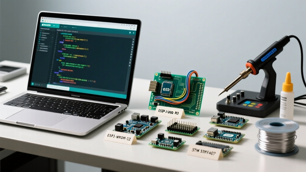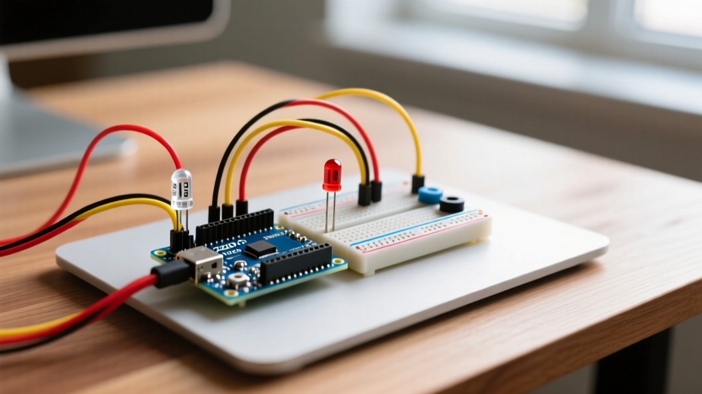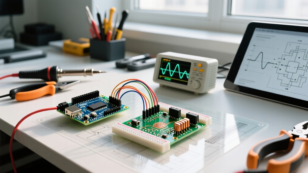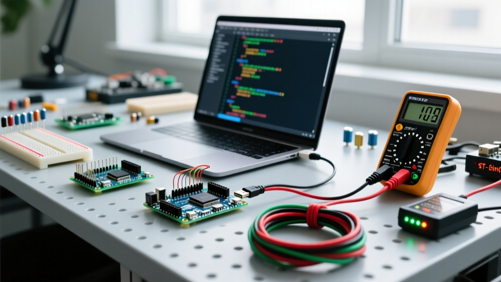

Transitioning from 8-bit AVR microcontrollers to 32-bit ARM Cortex-M architecture is a major milestone for any maker. The STM32duino core allows you to program STM32 chips using the familiar Arduino IDE. However, the hardware abstraction layer introduces unique failure modes. In this guide, we tackle the most persistent Arduino and STM32 upload errors, boot failures, and clock configuration issues plaguing makers in 2026.
1. ST-Link V2 'No Target Connected' or 'USB Device Not Recognized'
The ST-Link V2 is the gold standard for flashing and debugging STM32 boards via the Serial Wire Debug (SWD) protocol. However, clone ST-Link dongles (often priced around $3 to $5) frequently throw connection errors.
The 4-Wire SWD Wiring Trap
Unlike standard UART, SWD requires precise pin mapping. A common mistake is assuming the 4-pin header on the STM32F103C8T6 'Blue Pill' matches the ST-Link pinout exactly. It rarely does.
- SWDIO: Connect to PA13
- SWCLK: Connect to PA14
- GND: Connect to any Ground pin
- 3.3V (VDD): Connect to 3.3V. Critical: Pin 1 on the ST-Link is a voltage sense pin. Even if you are powering the Blue Pill via its own USB port, you MUST connect the ST-Link 3.3V pin to the target 3.3V rail so the debugger can sense the logic level. Omitting this causes the 'Target voltage too low' error.
For official ST-Link hardware, refer to the STMicroelectronics ST-Link V2 documentation to verify pinouts, as clone manufacturers frequently rearrange the 10-pin ARM JTAG header.
2. Serial Upload Failures and Boot Jumper Misconfiguration
If you lack an ST-Link, you can flash via a USB-to-Serial adapter (like the CP2102 or CH340G). This method relies on the MCU's embedded system bootloader, which is strictly governed by the BOOT0 and BOOT1 hardware pins.
Expert Rule of Thumb: The STM32F103 evaluates the BOOT pins only during a hard reset or power cycle. Changing jumpers while the board is running will have zero effect until you press the RESET button.
Correct Jumper Settings for Serial Flash
- Set BOOT0 to 1 (3.3V). This forces the MCU to boot from System Memory (the ROM bootloader).
- Set BOOT1 (PB2) to 0 (GND).
- Connect your Serial adapter TX to STM32 PA10 (RX), and RX to STM32 PA9 (TX).
- Press the RESET button on the STM32 board.
- Click 'Upload' in the Arduino IDE.
- Crucial Final Step: Once uploaded, move BOOT0 back to 0 (GND) and press RESET again, or your sketch will never run.
3. The 48MHz USB Clock Derivation Failure (HSE vs HSI)
One of the most baffling Arduino and STM32 issues occurs when a sketch compiles and uploads perfectly, but the USB Serial port refuses to enumerate on your PC. The device manager shows an 'Unknown USB Device'.
Why This Happens: The Counterfeit Crystal Problem
The STM32F103C8T6 USB peripheral requires a highly precise 48MHz clock. The Arduino core derives this by taking the 8MHz High-Speed External (HSE) crystal, multiplying it via the PLL to 72MHz, and dividing it by 1.5.
However, due to supply chain quirks that have persisted into 2026, many budget 'Blue Pill' boards are populated with 8MHz crystals that have incorrect load capacitance (e.g., 20pF instead of the required 10pF-15pF), or they use clone silicon (like CKS32 or GD32) that struggles to start the HSE oscillator reliably. When the HSE fails to start, the STM32 silently falls back to the internal 8MHz RC oscillator (HSI). The PLL math breaks down, the USB clock drifts, and the PC rejects the USB connection.
The Fix: Forcing HSI or Replacing the Crystal
If you suspect HSE failure, you can force the STM32duino core to use the internal oscillator, though USB may still be unstable. A better fix is to inspect the crystal load capacitors (C13 and C14) near the 8MHz can. Replacing them with 15pF or 18pF NP0/C0G ceramic capacitors often resolves the HSE startup failure instantly.
4. Comparison Matrix: STM32 Upload Methods in Arduino IDE
| Upload Method | Hardware Required | Speed | Reliability | Best Use Case |
|---|---|---|---|---|
| ST-Link (SWD) | ST-Link V2 ($3-$25) | Very Fast | High | Active development, hardware debugging (GDB) |
| Serial (UART) | USB-TTL Adapter ($2-$5) | Slow | Medium | One-off flashing, no SWD pins available |
| DFU (USB) | Native USB Port | Fast | Medium | Production boards with native USB (e.g., STM32F401) |
| HID Bootloader | Native USB Port | Fast | High | Custom PCBs requiring driverless Windows uploads |
5. Resolving 'arm-none-eabi-g++' Compilation Errors
When setting up the Arduino IDE for STM32, a frequent error is:
arm-none-eabi-g++: error: device-specs/specs-stm32f103c8: No such file or directory
This indicates a corrupted or mismatched STM32duino core installation. As of 2026, the STM32duino core relies on specific GCC ARM toolchains managed via the Board Manager. To fix this:
- Open Arduino IDE Preferences.
- Ensure the Additional Boards Manager URL points to the official repository found on the STM32duino Wiki Board Manager URL page.
- Navigate to
~/.arduino15/packages/STM32/hardware/stm32/(or your OS equivalent) and delete the existing core folder. - Reinstall the core via the Boards Manager. This forces a fresh download of the correct GCC ARM embedded toolchain and device specs.
6. DFU Mode and Windows Driver Conflicts
If you are using a board with native USB (like the STM32F401 'Black Pill' or STM32F411) and uploading via DFU, Windows often assigns a generic, incompatible driver to the 'STM32 BOOTLOADER' device in Device Manager. The Arduino IDE will report a dfu-util: Cannot open DFU device error.
The Fix: Download the open-source Zadig USB driver tool. Plug your board in while holding the BOOT0 button to enter DFU mode. Open Zadig, select 'STM32 BOOTLOADER' from the dropdown, and replace the default driver with WinUSB. Click 'Replace Driver'. The Arduino IDE will now seamlessly communicate with the DFU interface.
7. Debugging HardFaults and SRAM Overflows
Unlike the ATmega328P which simply hangs or resets when you run out of RAM, the STM32 Cortex-M3/M4 triggers a HardFault exception when it accesses invalid memory or overflows the stack. In the Arduino IDE, this usually manifests as a board that uploads successfully but immediately disconnects from the USB port or enters an infinite boot-loop.
Identifying Stack Overflows
The STM32F103C8T6 has 20KB of SRAM. If you declare large global arrays or use deep recursion, you will collide with the heap. To diagnose this without an SWD debugger, enable the 'Optimize for Debug (-Og)' option in the Arduino IDE Tools menu. This prevents the compiler from optimizing away your local variables, making the memory map easier to read.
Furthermore, you can implement a custom HardFault handler in your sketch to blink an LED in a specific SOS pattern or output the Program Counter (PC) register via a secondary UART before halting. This is a critical technique for field-deployed STM32 nodes where SWD access is sealed.
Summary Checklist for STM32 Troubleshooting
- Verify SWD wiring and ensure the ST-Link 3.3V sense pin is connected.
- Confirm BOOT0/BOOT1 jumper states and remember to press RESET after changing them.
- Investigate HSE crystal load capacitors if USB Serial fails to enumerate.
- Use Zadig to fix Windows DFU driver conflicts.
- Purge and reinstall the STM32duino core if GCC toolchain errors appear.