
Mastering the IR Receiver Arduino Workflow
Integrating an IR receiver Arduino setup into your maker projects unlocks wireless control using any standard television remote. Whether you are building a motorized camera slider, a smart LED lighting rig, or a home automation relay, infrared (IR) communication remains one of the most reliable and cost-effective wireless protocols available. Unlike basic 433MHz RF modules that lack native protocol standardization, IR remotes utilize established encoding standards like NEC, RC5, and Sony SIRC, making signal decoding highly predictable.
This comprehensive tutorial moves beyond basic blink sketches. We will cover exact hardware filtering requirements to eliminate phantom triggers, the modern object-oriented IRremote v4.x API, and protocol-specific edge cases that cause 90% of compilation and runtime failures in beginner projects.
Component Selection: TSOP38238 vs. VS1838B
Not all 38kHz IR receivers are created equal. The market is flooded with cheap clones that lack internal automatic gain control (AGC) and optical filters, leading to severe sunlight saturation and noisy data lines. Below is a technical comparison of the most common modules used in Arduino ecosystems.
| Model | Manufacturer | Supply Voltage | Internal Filter | Avg. Cost (2026) | Best Use Case |
|---|---|---|---|---|---|
| TSOP38238 | Vishay Semiconductors | 2.5V - 5.5V | Advanced AGC & Optical | $0.85 - $1.20 | Professional prototypes, high-noise environments |
| VS1838B | Various (Clones) | 3.3V - 5.0V | Basic | $0.10 - $0.25 | Low-budget hobby projects, indoor-only use |
| TSOP4838 | Vishay Semiconductors | 2.5V - 5.5V | Advanced AGC & Optical | $0.90 - $1.30 | Battery-operated devices (lower quiescent current) |
For reliable operation, we strongly recommend the TSOP38238. As noted in Vishay's official TSOP382 datasheet, this IC includes a suppression circuit specifically designed to block continuous 38kHz noise from fluorescent lighting and optically filter out visible light spectrum interference.
Hardware Wiring and the Critical Filter Circuit
A common failure mode in IR receiver Arduino circuits is the 'phantom trigger'—where the Arduino registers random button presses without any remote input. This is almost always caused by power supply ripple or electromagnetic interference (EMI) from nearby DC motors or switching regulators.
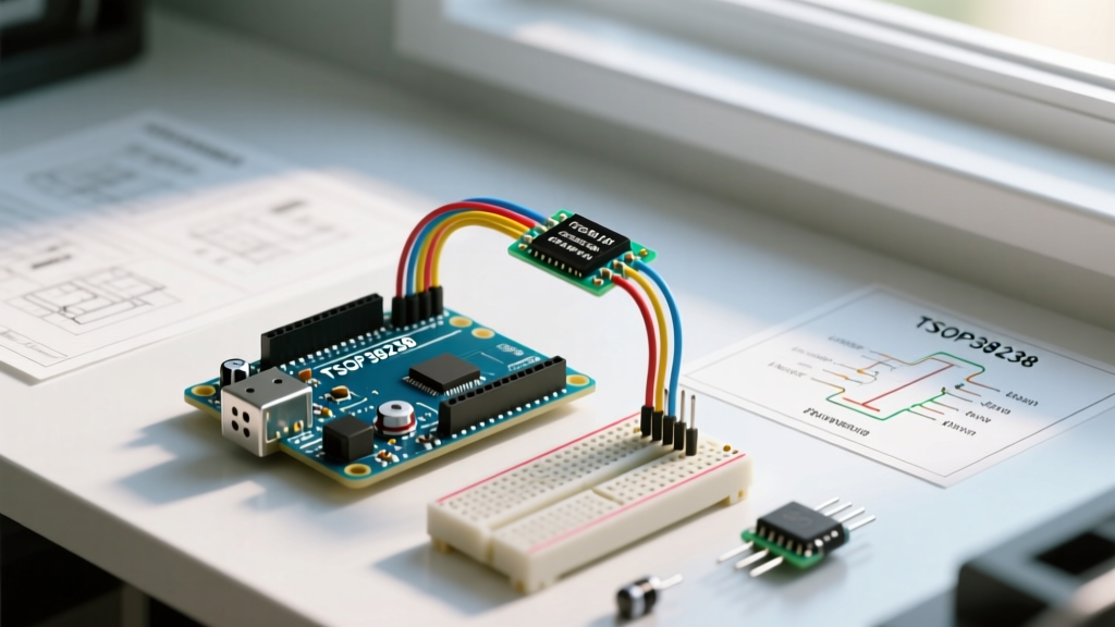
Standard Pinout (Facing the front of the sensor)
- Pin 1 (OUT): Digital Signal Output (Connect to Arduino Pin 11)
- Pin 2 (GND): Ground (Connect to Arduino GND)
- Pin 3 (VCC): Power Supply (Connect to Arduino 5V)
The Vishay RC Filter Requirement
To guarantee signal integrity, Vishay mandates an RC filter close to the receiver pins. If you are using a breadboard with long jumper wires, you must implement this filter:
- Place a 100Ω resistor in series with the VCC line, directly before the TSOP38238 VCC pin.
- Place a 4.7µF electrolytic capacitor across the VCC and GND pins of the receiver (after the resistor).
- Keep the physical distance between the capacitor and the receiver pins under 5mm.
Expert Insight: If you are powering your Arduino via USB from a cheap switching wall adapter, the 5V rail will be noisy. The 4.7µF capacitor acts as a local energy reservoir, smoothing out high-frequency voltage drops that would otherwise reset the receiver's internal AGC and cause data corruption.
Software: Configuring the IRremote Library (v4.x)
The Arduino IR ecosystem underwent a massive paradigm shift with the release of IRremote v3.0 and v4.0. If you are copying code from forums dated before 2022, it will fail to compile. The legacy irrecv.enableIRIn() and irrecv.decode(&results) methods have been deprecated in favor of a global IrReceiver object.
To install the correct library:
- Open the Arduino IDE and navigate to Sketch > Include Library > Manage Libraries.
- Search for IRremote by shirriff, z3t0, ArminJo.
- Install the latest v4.x release.
For a deeper dive into library management, refer to the official Arduino IRremote reference documentation.
Decoding the Signal: C++ Implementation
The following sketch initializes the receiver on Pin 11, decodes incoming signals, and prints the protocol type and hexadecimal command to the Serial Monitor. This is the foundational code for mapping remote buttons to physical actions.
#include

const int RECV_PIN = 11;
const int LED_PIN = 3;
bool ledState = false;

void setup() {
  Serial.begin(115200);
  pinMode(LED_PIN, OUTPUT);

  // Initialize the IRreceiver object (v4.x syntax)
  // ENABLE_LED_FEEDBACK blinks the onboard LED when a signal is received
  IrReceiver.begin(RECV_PIN, ENABLE_LED_FEEDBACK);
  Serial.println("IR Receiver Ready. Press a button on your remote.");
}

void loop() {
  if (IrReceiver.decode()) {
    // Print the decoded protocol and hex value
    Serial.print("Protocol: ");
    Serial.println(IrReceiver.decodedIRData.protocol);
    Serial.print("Hex Value: ");
    Serial.println(IrReceiver.decodedIRData.decodedRawData, HEX);

    // Example: Toggle LED on a specific NEC code
    if (IrReceiver.decodedIRData.decodedRawData == 0x20DF10EF) {
      ledState = !ledState;
      digitalWrite(LED_PIN, ledState ? HIGH : LOW);
      Serial.println("LED Toggled!");
    }

    // Resume receiving
    IrReceiver.resume();
  }
}
Understanding IR Protocols: NEC vs. RC5 vs. Sony
When you run the decoding sketch, you will notice different remotes output different data structures. Understanding these protocols is vital for setting up robust switch-case logic in your main loop.
- NEC Protocol: The most common standard (used by LG, Samsung, and generic LED strip remotes). It uses a 38kHz carrier, pulse-distance encoding, and transmits a 32-bit payload (16-bit address + 16-bit command). Hex codes typically look like
0x20DF10EF. - RC5 / RC6 (Philips): Uses Manchester bi-phase encoding. Unlike NEC, RC5 toggles a specific bit every time a button is held down or pressed repeatedly. If your code checks for an exact hex match, it will fail on alternating presses. You must mask the toggle bit in your logic.
- Sony SIRC: Operates at 40kHz (though often readable by 38kHz sensors with reduced range). It uses 12, 15, or 20-bit encoding depending on the device generation.
As detailed in Adafruit's comprehensive IR Sensor Guide, matching the remote's native carrier frequency to your sensor's bandpass filter is critical for achieving maximum range (up to 10 meters for NEC, compared to 3 meters for mismatched Sony remotes on a 38kHz sensor).
Troubleshooting Matrix: Edge Cases and Fixes
When your IR receiver Arduino circuit behaves erratically, use this diagnostic matrix to isolate the failure mode.
| Symptom | Probable Cause | Hardware / Software Fix |
|---|---|---|
| Random hex codes printing without remote input | Power rail noise / EMI | Install 100Ω resistor and 4.7µF capacitor on VCC line. |
| Range is limited to under 1 meter | Carrier frequency mismatch or low LED current | Verify remote is 38kHz. Increase IR LED current on the remote (check remote battery). |
Code compiles but IrReceiver.decode() is always false |
Timer conflict with other libraries | IRremote uses Timer 2 by default. Disable Servo.h or SoftwareSerial, or change IR timer in boarddefs.h. |
| Every other button press fails (RC5 Protocol) | Toggle bit interference | Bitwise AND the hex value with 0xF7FF to mask the RC5 toggle bit before comparison. |
| Sensor outputs solid 0xFFFFFFFF | Repeat code detected | This is normal for NEC 'button hold'. Ignore REPEAT flags in your switch logic. |
Advanced Implementation: Non-Blocking IR Polling
A frequent mistake in intermediate Arduino projects is placing blocking delays inside the IR execution logic. If your remote triggers a 2-second motor movement, using delay(2000) will cause the Arduino to miss any subsequent 'STOP' commands from the remote.
Always implement a state-machine approach using millis() for timing. Store the last received IR command in a global variable, and let the loop() function evaluate the current state against the elapsed time. This ensures the IrReceiver.decode() function is polled every few milliseconds, guaranteeing zero missed inputs during active mechanical operations.
Final Calibration Tips
Before soldering your final PCB or perfboard, test your specific remote's hex codes in the exact physical location where the device will live. Direct sunlight contains massive amounts of broadband infrared radiation. If your device is placed near a south-facing window, the TSOP38238's internal optical filter may become saturated, effectively blinding the sensor. In these high-ambient-IR environments, you must 3D print a physical shroud or hood over the sensor to block direct line-of-sight to the sun while maintaining a clear path to the user's remote control.