
Mastering Your Power Supply Arduino Configuration
Powering a microcontroller via a standard USB cable is sufficient for blinking an LED on a breadboard. However, the moment your project incorporates servos, stepper motors, relays, or high-draw sensor arrays, the USB 500mA limit becomes a severe bottleneck. Configuring a dedicated external power supply Arduino setup is a critical milestone for any maker transitioning from basic prototypes to robust, standalone embedded systems.
In this comprehensive configuration guide, we will dissect the internal power architecture of modern Arduino boards, calculate thermal dissipation limits, and provide step-by-step wiring instructions for both linear and switching power supply topologies. Whether you are using a classic Uno R3 or the modern Uno R4 Minima, understanding how to properly inject and regulate voltage will prevent catastrophic board failure and ensure stable operation in 2026 and beyond.
Understanding the Internal Power Architecture
Before connecting an external bench supply or wall adapter, you must understand how the Arduino routes power. Most standard AVR-based Arduinos feature four primary power input/output nodes:
- USB Port: Regulated 5V from your computer or a USB wall brick. Limited by an onboard polyfuse (typically 500mA on the Uno R3).
- Barrel Jack (DC In): Accepts unregulated DC voltage (recommended 7V-12V). Routes through a reverse-polarity protection diode and then into the onboard linear voltage regulator.
- Vin Pin: Electrically tied to the barrel jack input (post-diode). Ideal for connecting custom battery packs or bench power supplies directly.
- 5V Pin: The regulated 5V output rail. Warning: This pin bypasses the onboard regulator. You can use it to power peripherals, or back-feed a regulated 5V source directly into the board.
Critical Warning: Never apply voltage to the 5V pin while the board is simultaneously powered via the USB port or the Barrel Jack. This creates a power contention scenario that can permanently damage the ATmega328P microcontroller or the USB interface IC.
Board Specifications and Voltage Limits
The acceptable input voltage range varies significantly depending on the specific microcontroller board and its onboard regulator topology. According to the official Arduino Uno Rev3 documentation, the absolute maximum input voltage is 20V, but operating at this limit will cause the linear regulator to overheat almost instantly.
| Board Model | Recommended Vin | Absolute Max Vin | Onboard Regulator Type |
|---|---|---|---|
| Arduino Uno R3 | 7V - 12V | 20V | NCP1117-5.0 (Linear) |
| Arduino Uno R4 Minima | 6V - 24V | 24V | NCP1117ST50T3G (Linear) |
| Arduino Mega 2560 | 7V - 12V | 20V | NCP1117-5.0 (Linear) |
| Arduino Nano V3 | 7V - 12V | 20V | Linear (Clone dependent) |
The Thermal Bottleneck: Why Linear Regulators Fail
The most common failure mode when configuring a power supply Arduino setup is thermal shutdown of the onboard linear regulator. Linear regulators operate by dropping excess voltage as heat. As detailed in SparkFun's guide to voltage regulators, the power dissipated as heat (P) is calculated using the formula:
P = (Vin - Vout) × I
Where Vin is your input voltage, Vout is 5V, and I is the total current drawn from the 5V rail.
Real-World Thermal Scenario
Imagine you power your Uno R3 with a 12V wall adapter connected to the barrel jack. Your circuit includes the microcontroller (drawing ~40mA) and two standard SG90 micro servos powered directly from the Arduino's 5V pin (drawing ~400mA total under load). Your total current I is 440mA (0.44A).
- Calculation: P = (12V - 5V) × 0.44A = 3.08 Watts.
- The Reality: The SOT-223 package of the NCP1117 regulator on the Uno R3 can safely dissipate roughly 1.0W to 1.2W without a heatsink before hitting its internal thermal shutdown threshold (typically around 150°C junction temperature).
- Result: At 3.08W, the regulator will overheat in seconds, shut down, and your Arduino will continuously brownout and reset.
The Solution: If you must use a high input voltage (12V) and draw significant current, you must bypass the linear regulator entirely using a switching buck converter.
Configuration Method 1: The Switching Buck Converter (Recommended for High Draw)
For projects requiring more than 300mA on the 5V rail, a switching regulator is mandatory. Switching regulators (like the ubiquitous LM2596 or modern MP1584EN modules) step down voltage by rapidly switching a MOSFET and storing energy in an inductor, achieving 85-95% efficiency with minimal heat generation. You can purchase a pre-assembled MP1584EN buck converter module for roughly $2.50 to $4.00 in 2026.
Step-by-Step Buck Converter Wiring
- Prepare the Power Source: Connect your external DC power supply (e.g., a 12V 5A LED power supply, approx. $12) to the input terminals (IN+ and IN-) of the buck converter module.
- Calibrate the Output: Using a digital multimeter, probe the output terminals (OUT+ and OUT-). Turn the small brass trimpot on the module with a ceramic screwdriver until the multimeter reads exactly 5.00V.
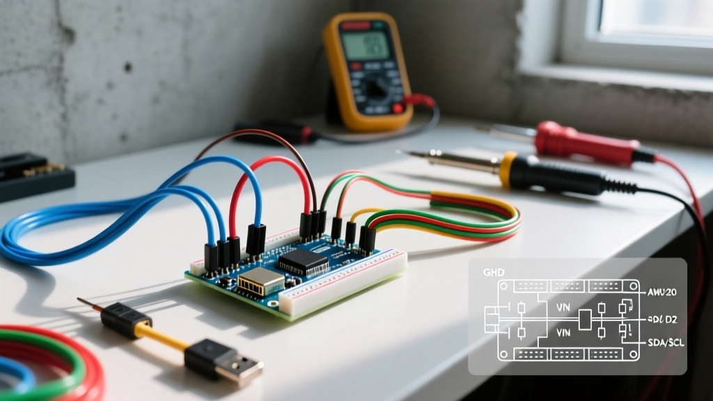
- Connect to Arduino: Connect the OUT+ of the buck converter directly to the 5V pin on the Arduino header. Connect OUT- to any GND pin.
- Isolate the Board: Ensure the Arduino is not plugged into USB or the barrel jack. The board is now powered directly via the 5V rail.
- Wire the Peripherals: Connect your high-draw servos, relays, or LED strips directly to the buck converter's output terminals, sharing a common ground with the Arduino. Do not route high peripheral current through the Arduino's fragile header pins.
Configuration Method 2: Direct Vin Injection (For Low-Draw Sensor Networks)
If your project consists solely of low-power I2C sensors, an LCD display, and a few LEDs (total 5V draw under 150mA), utilizing the onboard linear regulator via the Vin pin is perfectly safe and requires less wiring.
- Set your bench power supply to 9.0V (this provides a safe 4V dropout for the regulator while minimizing heat).
- Connect the positive lead to the Vin pin and the negative lead to GND.
- Ensure the power supply has a current limit set to at least 1A to handle inrush currents when the microcontroller boots and initializes peripherals.
Troubleshooting Power Supply Arduino Failure Modes
Even with a meticulous configuration, power anomalies can disrupt embedded systems. Use this diagnostic matrix to identify and resolve common issues:
| Symptom | Probable Cause | Actionable Fix |
|---|---|---|
| Arduino randomly resets when a motor engages. | Voltage sag on the 5V rail due to high inrush current. | Solder a 1000µF electrolytic capacitor across the 5V and GND rails near the motor driver. |
| Onboard 'ON' LED flickers or dims. | Linear regulator entering thermal protection. | Lower the Vin to 7.5V or migrate to an external switching buck converter. |
| USB serial port disconnects in the IDE. | Noise from external supply back-feeding into the USB interface IC. | Add a 0.1µF ceramic decoupling capacitor on the power input and ensure a star-ground topology. |
| Board fails to boot; 'L' LED stays solid. | Brownout detection (BOD) triggered during power-up. | Use a power supply with a soft-start feature or slower voltage ramp-up. |
Best Practices for Long-Term Reliability
When deploying an Arduino project in a permanent installation, such as an automated greenhouse or a home security node, power integrity is paramount. Follow these expert guidelines to ensure years of uninterrupted operation:
- Use Mean Well or TDK Enclosed Supplies: Avoid cheap, unbranded 'wall wart' adapters. Invest in an enclosed, actively cooled or high-efficiency switching supply like the Mean Well LRS-35-5 (approx. $14). These units feature built-in over-current, over-voltage, and short-circuit protection.
- Implement Star Grounding: Never daisy-chain high-current ground returns through the Arduino's GND header pins. Route all high-current grounds directly back to the main power supply's negative terminal, creating a single 'star' point.
- Add Transient Voltage Suppression (TVS): If your power supply Arduino setup is located in an industrial environment or outdoors, place a bidirectional TVS diode (e.g., SMAJ5.0A) across the 5V and GND lines to clamp inductive voltage spikes from nearby relays or solenoids.
- Fuse Protection: Always place an automotive blade fuse or a resettable PTC polyfuse on the positive lead immediately after the power supply output to protect against catastrophic short circuits in your field wiring.
Frequently Asked Questions
Can I power an Arduino with a 9V battery?
Yes, you can connect a standard 9V alkaline battery to the Vin pin or barrel jack. However, this is highly discouraged for anything beyond a brief demonstration. 9V batteries have very low current capacity (typically under 500mAh) and high internal resistance, meaning the voltage will sag rapidly under load, causing the Arduino to reset.
Is it safe to use a phone charger to power the Arduino via USB?
Modern USB-C or USB-A phone chargers are excellent, stable 5V power sources. A standard 2026 GaN charger can easily supply 2A to 3A. However, remember that the current is still limited by the Arduino's onboard USB polyfuse (500mA on older AVR boards). To draw more than 500mA from a phone charger, you must cut the 5V trace on the USB cable and wire it directly to your peripheral power bus.
What happens if I accidentally apply 12V to the 5V pin?
Applying 12V to the 5V pin will instantly destroy the ATmega328P microcontroller, the USB-to-Serial IC, and likely any connected 5V sensors. The 5V pin has no reverse-polarity or over-voltage protection. Always double-check your multimeter readings before connecting power to the 5V header.
For further reading on managing complex embedded power trees, consult the comprehensive resource on How to Power a Project to deepen your understanding of current budgets and battery life calculations.