
Mastering Inductive Sensing: The LDC Arduino Integration Guide
Inductive sensing is a robust, non-contact method for detecting metallic targets, measuring position, and identifying alloys. Unlike optical or capacitive sensors, inductive sensors are completely immune to environmental contaminants like dirt, oil, water, and dust. While the older LDC1000 was a popular entry point for makers, it is largely obsolete in 2026 due to its 8-bit resolution and single-channel limitation. Today, the Texas Instruments LDC1612 16-bit, dual-channel Inductance-to-Digital Converter is the gold standard for high-precision maker and prototyping projects.
This comprehensive tutorial will walk you through building a reliable LDC Arduino setup, covering the critical physics of LC tank circuits, precise I2C wiring, register-level configuration, and real-world troubleshooting.
Hardware Requirements and Sourcing
To build this project, you will need a few specific components. Do not substitute the ceramic capacitor type; this is a common point of failure.
- Microcontroller: Arduino Nano 33 IoT, Arduino Zero, or ESP32 (Must natively support 3.3V I2C logic).
- Sensor: LDC1612 Breakout Board (Available from ProtoCentral or generic suppliers for $18–$25).
- Inductive Coil: Custom PCB coil or off-the-shelf RF inductor (e.g., Coilcraft 1812CS series).
- Parallel Capacitor: 100pF to 1nF C0G/NP0 ceramic capacitor (X7R or Y5V will cause massive thermal drift).
- Logic Level Shifter: BSS138 bi-directional shifter (Only required if using a 5V Arduino Uno/Mega).
Critical Warning: The LDC1612 operates at 3.3V and its absolute maximum I2C voltage is 4.0V. Connecting SDA/SCL directly to a 5V Arduino Uno without a level shifter will permanently destroy the sensor's I2C transceiver.
Step-by-Step Wiring Guide
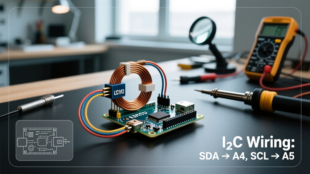
Assuming you are using a native 3.3V Arduino board (like the Nano 33 IoT), the wiring is straightforward. The LDC1612 communicates via I2C, and the Arduino Wire library handles the low-level protocol.
Pinout Connections
| LDC1612 Pin | Arduino Nano 33 IoT Pin | Notes |
|---|---|---|
| VCC | 3.3V | Ensure clean power; use a 100nF decoupling cap near the pin. |
| GND | GND | Connect to a common ground plane. |
| SDA | SDA (A4) | Requires 4.7kΩ pull-up to 3.3V if breakout lacks them. |
| SCL | SCL (A5) | Requires 4.7kΩ pull-up to 3.3V if breakout lacks them. |
| INTB | D2 | Active low interrupt (optional, for data-ready polling). |
| ADDR | GND | Ties I2C address to 0x2A. Tie to VCC for 0x2B. |
The Secret Sauce: LC Tank Coil Design
The most common reason an LDC Arduino project fails is poor coil design. The LDC1612 does not measure inductance directly; it measures the resonant frequency of an LC tank circuit formed by your external coil (L) and parallel capacitor (C). When a metallic target enters the magnetic field, eddy currents are induced in the metal, which effectively reduces the inductance and shifts the resonant frequency upward.
PCB Coil Best Practices
If you are etching your own PCB coil, follow these strict guidelines to maximize the Quality Factor (Q):
- Layer Count: Use a 2-layer or 4-layer PCB. A 4-layer board allows you to route the inner layers in parallel, doubling the inductance without increasing the footprint.
- Trace Width and Spacing: Use 0.15mm (6 mil) trace width and 0.15mm spacing. Wider traces lower the series resistance (Rp), improving the Q factor.
- Outer Diameter: The sensing range is roughly 50% of the coil's outer diameter. A 10mm coil yields a reliable sensing distance of about 5mm.
- Fill Ratio: Keep the inner diameter at least 20% of the outer diameter to avoid wasting space on the center where magnetic field contribution is negligible.
Selecting the Parallel Capacitor
You must place a capacitor in parallel with the coil to form the resonant tank. The target resonant frequency should be between 1 MHz and 10 MHz. Use the formula f = 1 / (2π√(LC)) to calculate your values. Always use C0G (NP0) dielectric capacitors. Standard X7R capacitors exhibit severe capacitance shifts with temperature and applied AC voltage, which the LDC will interpret as a false target proximity reading.
Arduino Code: Register Configuration and Reading
While wrapper libraries exist, writing directly to the LDC1612 registers provides superior control and debugging capability. The sensor uses 16-bit registers accessed via standard I2C.
Initialization and Drive Current
Before reading data, you must configure the DRIVE_CURRENT register (Address 0x1E). If the drive current is too low, the oscillation will die out. If it is too high, the sensor will flag an amplitude error.
#include <Wire.h>

#define LDC_ADDR 0x2A
#define REG_DATA_CH0_MSB 0x00
#define REG_DATA_CH0_LSB 0x01
#define REG_DRIVE_CH0 0x1E
#define REG_STATUS 0x18

void setup() {
  Serial.begin(115200);
  Wire.begin();

  // Set Drive Current for Channel 0
  // Value 0x9000 is a safe starting point for most mid-sized PCB coils
  writeRegister16(REG_DRIVE_CH0, 0x9000);

  // Configure Mux and Sleep modes (Register 0x1B)
  // 0x020C: Channel 0 active, 10MHz reference, normal operation
  writeRegister16(0x1B, 0x020C);
}

void loop() {
  uint16_t status = readRegister16(REG_STATUS);

  if ((status & 0x0008) == 0) { // Check if new data is ready (DRDY bit)
    uint16_t msb = readRegister16(REG_DATA_CH0_MSB);
    uint16_t lsb = readRegister16(REG_DATA_CH0_LSB);

    // Mask out the status flags from the MSB
    uint32_t rawData = ((uint32_t)(msb & 0x0FFF) << 16) | lsb;

    Serial.print('Raw Sensor Value: ');
    Serial.println(rawData);
  }
  delay(10);
}

void writeRegister16(uint8_t reg, uint16_t val) {
  Wire.beginTransmission(LDC_ADDR);
  Wire.write(reg);
  Wire.write((val >> 8) & 0xFF);
  Wire.write(val & 0xFF);
  Wire.endTransmission();
}

uint16_t readRegister16(uint8_t reg) {
  Wire.beginTransmission(LDC_ADDR);
  Wire.write(reg);
  Wire.endTransmission(false);
  Wire.requestFrom(LDC_ADDR, 2);
  uint16_t val = (Wire.read() << 8) | Wire.read();
  return val;
}
LDC Sensor Comparison Matrix
When planning your inductive sensing project, selecting the right silicon is critical. Here is how the major TI LDC chips compare for Arduino integration in 2026.
| Feature | LDC1000 (Legacy) | LDC1312 | LDC1612 (Recommended) |
|---|---|---|---|
| Resolution | 8-bit (Inductance) / 9-bit (Rp) | 12-bit | 16-bit / 28-bit (with ext. clock) |
| Channels | 1 | 2 | 2 |
| Max Sample Rate | 12 kSPS | 4.2 kSPS | 4.2 kSPS |
| Typical Breakout Price | $25 (Hard to find) | $14 | $18 - $25 |
| Best Use Case | Metal type identification | Basic proximity / counting | High-res position / micrometer sensing |
Advanced Troubleshooting and Edge Cases
Inductive sensing is highly sensitive to parasitic elements. If your LDC Arduino setup is yielding erratic data, check these specific failure modes:
1. The Amplitude Error (ERR_AMP)
If the Status Register (0x18) returns a value with the ERR_AMP bit set, your LC tank's oscillation amplitude is outside the acceptable window (typically 1.2V to 1.9V peak). Fix: Adjust the DRIVE_CURRENT register. Increase the hex value if the amplitude is too low, or decrease it if the sensor is overdriving the tank.
2. Watchdog Timeouts (ERR_WD)
This occurs when the sensor's internal watchdog timer expires because the oscillation frequency dropped below the minimum threshold (usually around 500 kHz). Fix: Your coil inductance or parallel capacitance is too high. Reduce the parallel capacitor value or decrease the number of turns on your PCB coil.
3. Thermal Drift and Environmental Noise
If your baseline reading shifts as the room heats up, you are likely using an X7R capacitor or your PCB coil traces are too thin, causing high thermal coefficient of resistance. Furthermore, keep the LDC1612 and the LC tank away from switching power supplies (like buck converters), as high-frequency EMI will couple into the high-impedance tank and corrupt the 16-bit ADC readings.
Conclusion
Integrating an LDC1612 into an Arduino project unlocks industrial-grade position and proximity sensing capabilities on a maker budget. By respecting the 3.3V logic requirements, strictly utilizing C0G capacitors, and tuning the drive current registers via direct I2C manipulation, you can achieve sub-micron resolution in your next mechanical or robotic design.